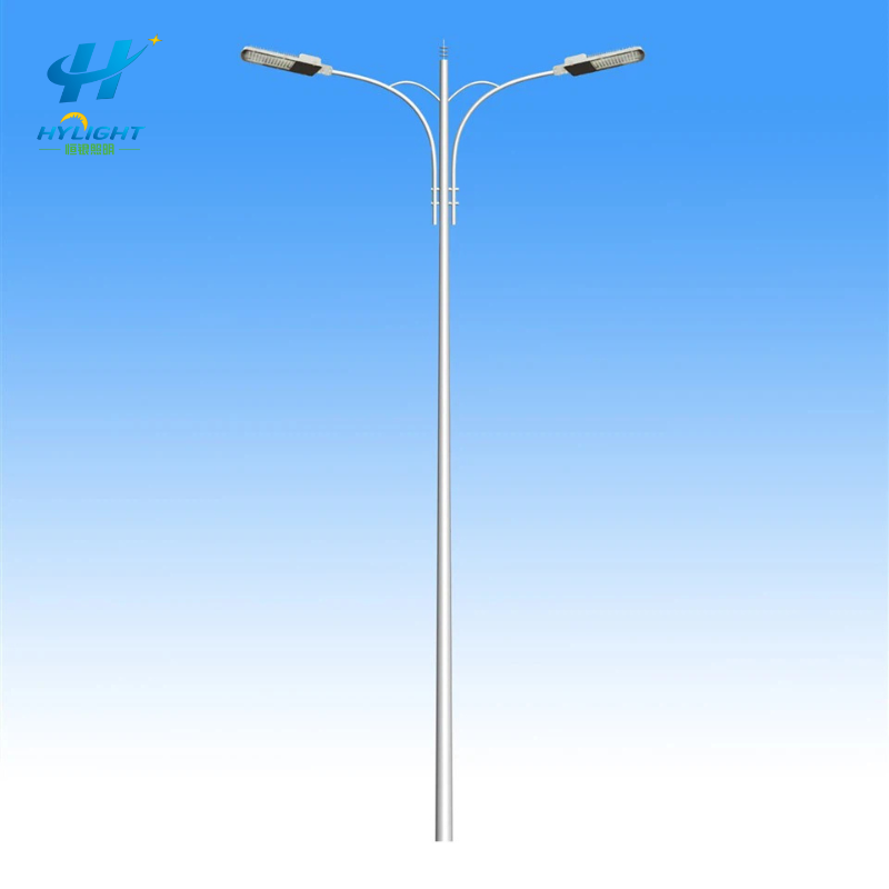
A street light pole can be correctly fabricated and still arrive at a foundation it cannot fit. The recurring causes are rarely mysterious: an obsolete bolt-circle drawing, the wrong projection, a conduit that conflicts with the base plate, an unconfirmed handhole direction, missing pole reactions, or concrete poured before the pole-specific template was approved.
For municipal buyers, EPC contractors, civil teams, distributors, and installers, the safest procurement unit is therefore not only the pole. It is a controlled foundation interface package that connects the pole design, civil design, anchor assembly, electrical entry, inspection points, and final records. This guide explains what that package should contain and how to approve it without treating a generic footing detail as a universal design.
GEO Summary
- Freeze the site, pole, fixture, bracket, accessory, wind, terrain, corrosion, and foundation-design inputs before releasing anchor bolts or concrete drawings.
- Require a pole-specific base drawing, anchor-bolt schedule, identified template, cable-entry and handhole orientation, and signed base reactions for the governing load cases.
- The project civil or structural engineer should design or approve the actual foundation from confirmed reactions and site data. A supplier drawing should not be mistaken for geotechnical or foundation approval.
- Put formal hold points before the pour, after the anchor assembly is set, before erection, and at final acceptance. Record bolt position, projection, orientation, concrete information, pole plumbness, hardware, coating repair, and as-built changes.
- Do not solve a mismatch by slotting a base plate, bending anchors, flame-cutting holes, or using an unengineered adaptor. Raise a nonconformance and obtain a documented repair design.
- For a project-specific proposal, send Henlyte the site location, pole schedule, luminaire and arm data, drawings, design criteria, soil information, quantity, destination, and required approval dates.
The Short Answer: What Must Be Approved Before Concrete Is Poured?
At minimum, the construction team should hold an approved-for-construction foundation drawing, the current pole base and anchor-bolt drawing, a uniquely identified physical template or setting frame, the pole manufacturer’s confirmed base reactions and load assumptions, the conduit/earthing arrangement, and an inspection checklist. The drawing revisions, pole marks, template identification, and purchase lines must agree.
If any of those items is provisional, the concrete release is provisional too. A fast pour based on a preliminary catalogue dimension can create a slow and expensive field correction.
Why the Foundation Interface Is a Procurement Package
The pole supplier normally controls the shaft, base plate, welds, anchor assembly supplied with the pole, and the load/reaction information generated for the offered configuration. The project designer controls the applicable design criteria and approval. The civil or structural engineer controls the foundation suited to the reactions, soil, slope, drainage, and local construction rules. The electrical team controls cable routes, conduit, grounding, and access. The installer controls setting, survey, erection, tightening, protection, and records.
These responsibilities overlap at one small area beneath the pole. If the interface is managed only through emails and catalogue pages, each party can work from a different assumption. A document index and approval matrix make the boundaries visible.
| Interface item | Typical originator | Required reviewer or approver | Acceptance evidence |
|---|---|---|---|
| Pole schedule and mounted equipment | Lighting or project designer | Owner, lighting designer, pole engineer | Approved pole mark, height, arms, fixtures, accessories |
| Structural criteria and pole reactions | Pole engineer or qualified designer | Project structural/civil engineer | Load basis and signed reaction table tied to pole revision |
| Foundation geometry and reinforcement | Project civil/structural engineer | Authority or engineer of record | Approved-for-construction foundation drawing |
| Base plate and anchor assembly | Pole manufacturer | Civil engineer and installer | Dimensioned drawing, bill of materials, template ID |
| Conduit, cable window, and grounding | Electrical designer | Civil engineer and installer | Coordinated section and site inspection record |
| Setting, survey, erection, and repair | Contractor | Site engineer or inspector | Inspection and test plan records plus as-built survey |
The exact allocation varies by contract. The important point is to name it before manufacture and civil work begin.
Freeze the Design Inputs Before Issuing Anchor Bolts
An anchor-bolt release is an engineering release, not an accessory shipment. Before approval, issue a controlled input sheet that identifies the installation location, pole mark, nominal height, shaft and base type, luminaire quantity and mass, bracket outreach, orientation, signs, banners, cameras, solar panels, decorative attachments, and any future equipment included in the design.
The sheet should also state the design standard or authority requirement, design wind information, terrain/exposure assumptions, importance or reliability requirements where applicable, topography, ice or other environmental loads if relevant, breakaway requirements, corrosion category, temperature, and permitted deflection or vibration criteria. The pole engineer should list the assumptions used to calculate reactions rather than sending unexplained numbers.
Foundation inputs are equally important: geotechnical parameters, groundwater, slope, finished grade, pavement buildup, drainage, nearby utilities, barrier or clear-zone conditions, excavation limits, and concrete/reinforcement requirements. If a standard agency footing is proposed, the designer should confirm that the project falls within that standard detail’s stated limits.
Do not use a general foundation depth from a sales page as a project design. Pole height alone does not establish soil capacity, moment, uplift, shear, reinforcement, durability, or constructability.
Require a Traceable Base-Reaction Schedule
The foundation designer needs reactions at a clearly defined interface and for clearly identified load combinations. Ask for axial force, shear, bending moment, and torsion as applicable, with signs or envelopes explained. The schedule should identify whether values are service, working, factored, or ultimate and name the code basis used. Units must be unambiguous.
Each reaction row should map to a pole mark and revision. If the luminaire, arm length, equipment area, sign, solar panel, camera, or pole geometry changes, the supplier should state whether the reactions and anchor design remain valid. “Same pole height” is not a technical confirmation.
Where the project has multiple pole families, use a controlled matrix instead of assuming the largest pole covers every case. A short pole with a large sign or panel can govern a different load effect from a taller lighting-only pole.
Minimum Street Light Pole Base and Anchor Drawing
The base drawing must be dimensioned for manufacture and site setting, not only illustrated. It should include the following fields or explicitly mark them not applicable.
| Drawing field | What to show | Coordination risk controlled |
|---|---|---|
| Pole/base identity | Pole mark, shaft type, base drawing number, revision | Wrong foundation or template used for a similar pole |
| Base plate | Outside dimensions, thickness, hole size and pattern, orientation datum | Plate does not fit anchors or conflicts with conduit |
| Anchor pattern | Quantity, bolt-circle or coordinates, tolerance basis, template ID | Anchors set to a nominal or obsolete pattern |
| Anchor assembly | Diameter, material/grade, length, embedment form, thread, nuts, washers, coating | Hardware is substituted or installed in the wrong order |
| Projection | Required range referenced to finished foundation level | Insufficient thread, excessive exposure, or base-cover conflict |
| Cable entry | Central or offset conduit zone, clear opening, bend constraints | Conduit blocks the plate, washers, or wiring access |
| Orientation | Road, arm, door/handhole, base seam, and template datum | Pole door or arm faces the wrong direction |
| Base support | Approved leveling/grout arrangement and drainage note | Uncontrolled gaps, water traps, or unintended load path |
| Grounding | Earthing lug or conductor route and coordination note | Ground conductor omitted or trapped after erection |
| Finish | Galvanizing/coating extent, protected threads, permitted repair method | Corrosion protection damaged during setting or tightening |
The drawing should say whether the template is temporary, sacrificial, or part of a reusable setting frame. It should identify what ships in the advance anchor package and what remains with the pole shipment.
Henlyte’s light pole range and LED street light pole category provide useful starting points for defining the offered pole family. The approved project drawing, however, must control over a generic category page.
Use a Controlled Drawing-Approval Sequence
A practical approval sequence prevents the civil team from building around a moving pole design.
- The buyer issues the pole schedule, mounted-equipment data, site criteria, geotechnical information, and interface dates.
- The pole supplier returns the design basis, exceptions, preliminary base arrangement, reaction schedule, and document register.
- The civil/electrical teams coordinate the foundation, conduit, grounding, finished level, orientation, and access.
- The pole supplier incorporates agreed interface dimensions and returns a revision for approval.
- The engineer of record approves the project foundation; the authorized reviewer approves the pole/anchor interface.
- The contract administrator marks the exact anchor/template documents approved for advance release.
- The factory and site teams acknowledge the same revision before manufacture, dispatch, and concrete placement.
- Any later change triggers an interface-impact check and a formal revision or written confirmation of no impact.
Keep “approved”, “approved with comments”, “revise and resubmit”, and “approved for anchor release” as distinct statuses. A comment-resolution email should not silently replace the controlled drawing.
Advance Anchor-Bolt Release Without Losing Configuration Control
Projects often need foundations before poles are complete. Early release can protect the schedule if the anchor package is treated as serialized project material.
Label each bundle with project, pole mark or family, drawing number and revision, template number, bolt quantity, hardware list, coating, and dispatch date. Include a packing photo and dimensional inspection record. The site receiving team should compare the physical template and hardware to the release document before distributing them across the project.
Do not print a web diagram at an unknown scale and use it as a setting template. Use the supplied pole-specific template or an approved fabricated setting frame checked against the controlled dimensions. Store anchors dry, protect threads, and prevent site bending, welding, or coating removal unless an approved procedure requires it.
Pre-Pour Hold Point
The best time to correct an anchor assembly is before concrete. Make the pre-pour check a witnessed hold point for the relevant sample or every foundation, depending on the quality plan.
- Confirm foundation location, offset, finished level, diameter or plan dimensions, depth, reinforcement, cover, and excavation condition against the approved drawing.
- Confirm the current pole mark, base drawing revision, template ID, bolt count, pattern, projection, verticality, orientation datum, and hardware protection.
- Check that the assembly is restrained at more than one level where required and cannot rotate, spread, or float during placement.
- Confirm conduit position, quantity, diameter, bend/clearance, draw wire, drainage, grounding conductor, and separation from reinforcement and anchors.
- Verify concrete specification, delivery/placement plan, inspection access, sampling requirements, and curing/protection plan.
- Photograph a readable identification board together with the overall assembly, orientation, projection, reinforcement, conduit, and survey reference.
The inspector should record actual measurements rather than tick “OK” without data. The release signature should identify the drawing revision used.
Post-Pour Survey and Foundation Release
After the concrete has reached the contractually required condition, remove temporary setting parts as instructed and survey the anchors. Record coordinates or bolt circle, relative level, projection, verticality, template orientation, conduit condition, foundation top level, and visible damage. Protect threads and openings until erection.
Compare the results with the approved tolerance basis before the pole shipment is called forward. If a discrepancy exists, issue a nonconformance with measurements and photographs. The pole supplier, anchor designer, and engineer of record can then assess options using the actual data.
Never normalize field alteration because “the pole almost fits.” Slotting base holes, bending cast-in anchors, heating steel, omitting washers, stacking uncontrolled shims, or forcing the plate can change the intended load path and durability. Any adaptor, post-installed anchor, local plate modification, or foundation replacement must be engineered and approved for that condition.
Pole Erection, Leveling, Tightening, and Grout
Before lifting, verify the pole ID, base plate, anchor pattern, coating, door orientation, bracket orientation, mass, lift plan, and foundation release. Clean the threads without damaging the coating and confirm that the specified nuts and washers run correctly.
The leveling, nut arrangement, tightening method, sequence, lubrication condition, required torque or tension, and use of grout must follow the approved project and manufacturer instructions. These details are not interchangeable across every base design. Record the method and final condition instead of relying on an unrecorded “tight” judgment.
Check pole plumbness in two directions at the specified stage, recheck after mounted equipment is installed if required, and document the result. If grout is specified, control material, preparation, placement, thickness, ventilation or drainage details, curing, and inspection. If grout is not specified, do not add it as an improvised cosmetic repair.
Electrical Entry, Grounding, Drainage, and Access
The foundation detail should allow the cable to enter without violating bending radius or rubbing on sharp edges. The conduit must not prevent installation of the plate, washers, nuts, base cover, or internal terminals. Confirm that maintenance staff can reach the handhole and that its orientation is safe relative to traffic and working space.
Record continuity and grounding checks required by the electrical specification. Seal or drain entries according to the approved arrangement; an unplanned seal can trap water, while an unplanned opening can admit debris and pests. Coordinate base covers so they do not hide incomplete tightening, damaged coating, or standing water before inspection.
Projects combining poles and roadway luminaires can review Henlyte’s LED street light range while coordinating fixture mass, wind area, mounting, cable, and driver access with the structural package.
Coating Protection and Repair Evidence
Hot-dip galvanized poles and anchors can be damaged by transport, lifting, thread cleaning, tools, and site welding. The inspection plan should define what counts as damage, the permitted repair standard or project procedure, surface preparation, repair material, minimum coverage, and acceptance evidence.
A hot-dip galvanized steel light pole still needs protected storage, non-damaging slings, correct hardware handling, and documented touch-up. Paint or zinc-rich material applied over dirt, moisture, or loose coating is not a verified repair.
Foundation Interface Inspection and Test Plan
Use an inspection and test plan that follows the interface from submittal through handover.
| Stage | Suggested control point | Record |
|---|---|---|
| Design input | Review pole schedule, equipment, criteria, geotechnical and electrical inputs | Approved input sheet and assumptions register |
| Interface approval | Check reactions, base drawing, anchor schedule, template, conduit and foundation | Approved drawings and comment closeout |
| Factory anchor package | Verify dimensions, material, coating, hardware, template and labels | Inspection record, certificates, packing photos |
| Site receipt | Match package to pole mark and revision; inspect damage and quantity | Receiving report and quarantine log if needed |
| Pre-pour | Witness survey, reinforcement, anchors, projection, orientation, conduit and grounding | Measured checklist and photographs |
| Post-pour | Survey anchors and foundation level; inspect threads and openings | As-built survey and release status |
| Erection | Verify pole ID, lifting, orientation, leveling, tightening and coating | Erection checklist and tightening record |
| Final acceptance | Confirm plumbness, hardware, access, grounding, drainage, labels and documents | Punch-list closeout and as-built package |
Street Light Pole RFQ Checklist
Send enough information for the supplier to return an engineered interface rather than a nominal pole price.
- Project country, installation coordinates, authority, applicable specifications, and approval workflow.
- Pole schedule with quantity, height, shaft shape, material, base type, arm geometry, luminaire, signs, cameras, panels, banners, and future attachments.
- Luminaire and bracket mass, projected area, center of gravity, quantity, orientation, and mounting detail.
- Wind, terrain/exposure, topography, temperature, ice or other environmental criteria required by the project.
- Geotechnical report, slope, groundwater, finished grade, pavement, drainage, utilities, barrier/clear-zone conditions, and foundation constraints.
- Required reaction format, design calculation, material certificates, welding/NDT, coating, anchor, template, drawing, inspection, packing, and warranty documents.
- Cable/conduit, handhole, terminal, grounding, door orientation, base-cover, and maintenance-access requirements.
- Anchor-bolt advance-release date, drawing-approval dates, delivery sequence, destination, Incoterm, and installation responsibilities.
Henlyte’s roadside light pole page can help identify a product direction, but the RFQ should still include the project load and interface data above.
Common Foundation Interface Red Flags
- A quotation supplies pole height and thickness but no load assumptions or base reactions.
- The foundation drawing and base drawing use different bolt-circle, projection, or finished-level references.
- The template has no project, pole, drawing, or revision identification.
- Anchor bolts are released before the mounted equipment and design criteria are frozen.
- The civil detail copies a standard footing without checking its soil, slope, load, and authority limits.
- Conduit, grounding, door orientation, and base-cover clearance are absent from the coordination drawing.
- The inspection form has no measured values, photographs, survey reference, or drawing revision.
- A mismatch is corrected by cutting, bending, heating, slotting, or omitting hardware without an approved repair design.
- Final handover lacks the reaction table, approved drawings, certificates, concrete records, survey, tightening record, coating repair, and as-built changes.
Image Suggestions
Use the existing Henlyte street light pole image as the featured image with the alt text “street light pole foundation interface and anchor-bolt drawing review.” Add an original annotated diagram showing the pole base plate, bolt circle, projection, template ID, conduit zone, handhole direction, finished level, and north/road datum. A second image can be a four-stage inspection strip: factory anchor package, pre-pour assembly, post-pour survey, and erected pole acceptance. Any sample dimensions should be clearly labeled illustrative, not project design values.
FAQ
Who designs the foundation for a street light pole?
The project civil or structural engineer should design or approve the actual foundation using confirmed pole reactions, site criteria, geotechnical data, slope, drainage, and local requirements. The pole supplier should provide configuration-specific reactions and base/anchor information, but those documents do not replace site foundation engineering unless the contract explicitly assigns and verifies that scope.
Can a contractor use a generic anchor-bolt template from the internet?
No generic diagram should be assumed to match the purchased pole. Use the supplied pole-specific template or an approved setting frame checked against the current controlled drawing. Confirm the template ID, bolt pattern, projection, and orientation before the pour.
What must the pole base reaction table include?
It should identify the pole mark and revision, load assumptions, governing combinations, units, reaction location, and applicable axial, shear, moment, and torsion values. It should also say whether the values are service or factored and which design basis was used.
What happens if the cast-in anchor bolts do not match the base plate?
Measure and document the actual condition, quarantine the affected foundation or pole, and issue a nonconformance. An engineer should assess a project-specific solution such as foundation replacement, an engineered adaptor, or qualified post-installed anchorage. Do not bend anchors or enlarge holes without approval.
Should the pole base be grouted?
Follow the approved structural detail and pole-manufacturer instructions. Some arrangements use grout and others use a different support/ventilation detail. If grout is required, its material, preparation, placement, drainage, cure, and inspection should be specified; it should not be added or omitted by habit.
Which records should be handed over with the installed pole?
Provide the approved input sheet, calculations or reaction schedule, pole/base/foundation drawings, anchor and material certificates, factory and receiving inspections, concrete records, pre-pour and post-pour measurements, survey, erection/tightening and coating-repair records, grounding checks, photographs, nonconformance closeout, and final as-built revisions required by the contract.
Inquiry CTA
Planning a municipal road, industrial estate, parking area, campus, or infrastructure lighting project? Send Henlyte the pole schedule, luminaire and arm data, site location, design criteria, geotechnical/foundation information, cable-entry requirements, quantity, destination, and approval dates. Use the Henlyte project inquiry form and include “street light pole foundation interface” so the team can identify the required drawings, reaction inputs, anchor package, and missing coordination data before quotation.