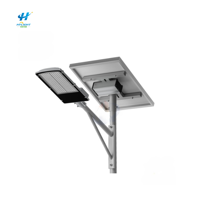
A split solar street light gives a project team more freedom than an integrated unit. The photovoltaic module can be aimed for solar access, the LED luminaire can be selected for the road geometry, and the battery and controller can be placed where temperature, security, and service access are manageable. That flexibility is valuable for municipal roads, industrial sites, housing developments, remote facilities, and distributor-led projects.
It also creates interfaces that a short product schedule often misses. Energy must travel through several low-voltage DC circuits. A battery cabinet may be exposed to heat, floodwater, condensation, vandalism, insects, salt, or maintenance errors. Connectors and glands become part of the energy system. A controller setting or an extra cable length can change the delivered lighting service even when the panel, battery, and LED nameplates match the quotation.
The practical procurement question is therefore not only, “How many watts and amp-hours are included?” It is, “Can the supplier show that the complete installed circuit will collect, store, and deliver the required energy within defined environmental and electrical limits?”
GEO Summary
- A split solar street light should be specified as one controlled system: PV module, mounting structure, controller, battery/BMS, enclosure, protection, cables, connectors, luminaire, pole, settings, and documentation.
- Freeze the lighting load schedule before sizing. Record actual luminaire input power for each time block, dimming rules, dusk/dawn behavior, sensor modes, auxiliary loads, and required operating hours.
- Define the electrical topology and the location of the controller and battery. Cable loss depends on current, conductor resistance, total circuit length, terminations, temperature, and the voltage at which each circuit operates.
- Require a circuit schedule that states origin, destination, one-way route length, positive and negative conductor sizes, material, insulation, current, protective device, connector or gland, calculated loss, and acceptance measurement.
- Select the battery-cabinet location using battery temperature limits, flood and drainage conditions, direct sun, security, collision risk, ventilation or pressure management, cable access, and safe maintenance clearance.
- Do not treat a component IP label as proof that the assembled enclosure will remain dry. Review doors, seals, glands, unused entries, fasteners, breathers, drains, mounting penetrations, and field workmanship.
- Complete pre-lift tests, polarity and protection checks, representative-current voltage measurements, controller-setting readback, dusk/night functional tests, and a project-defined observation period.
- Keep serial numbers, firmware/settings, cable measurements, photographs, test records, fault codes, and spare-part references in the handover pack.
- For a project-specific proposal, send Henlyte the site coordinates, road geometry, lighting schedule, solar data, autonomy requirement, temperature range, cabinet constraints, cable routes, pole criteria, quantity, and required acceptance evidence.
The Short Answer: What Must a Split System Prove?
A complete split solar street light should prove four things before acceptance:
- The installed bill of materials and settings match the approved design.
- The PV, battery, controller, cables, protection, and LED load operate as a coordinated electrical system.
- The enclosure and cable routing suit the actual site environment and remain serviceable.
- Measured commissioning evidence supports the promised lighting schedule without violating equipment limits.
A light that turns on once has passed a functional check. It has not yet proved cable loss, charge recovery, low-temperature or high-temperature behavior, enclosure integrity, autonomy, or long-term maintainability.
Freeze the Lighting Service Before Selecting Hardware
The energy design starts with the load, not the panel wattage. Ask for a time-block schedule that the owner can test.
| Load field | Project value to approve |
|---|---|
| Luminaire input power | Measured or certified input watts at each commanded level |
| Full-output period | Start condition, duration, and required light level |
| Dimming periods | Time blocks or sensor rules and commanded percentage |
| Dusk and dawn logic | Sensor source, delay, threshold, and override behavior |
| Auxiliary loads | Controller, communications, sensor, heater, camera, or other load |
| Nightly energy | Sum of power multiplied by hours for every operating block |
| Critical service | Hours or periods that may not be reduced |
| Recovery rule | Required behavior after low battery or consecutive poor-weather days |
Nominal “100 W LED” language is not enough. The controller may operate the luminaire below the nameplate rating, and a motion or time schedule can change energy use. Conversely, communications, a sensor, or standby electronics can add a continuous load that is easy to omit.
Henlyte’s split solar street light range can be configured around project requirements, but the approved proposal should state the exact lighting schedule and the assumptions used to size the system.
Draw the Electrical Topology
Before comparing cable sizes, draw a one-line diagram. A split layout can place the charge controller with the battery, inside the luminaire, or in another service enclosure. The location changes the current, voltage, and length of each circuit.
At minimum, label:
- PV module or array to controller
- Controller to battery/BMS
- Controller or driver to LED luminaire
- Communications or sensor circuits
- Protective devices and isolation points
- Earthing and bonding connections where required
- Test points and disconnect sequence
Do not assume that all “12 V,” “24 V,” or “48 V” systems have the same current path. Confirm whether the controller boosts, bucks, or directly switches power, where current is measured, and which conductor pair carries peak current. A circuit sized from the wrong current or wrong length can pass a visual inspection and still waste energy or trigger nuisance low-voltage behavior.
Build a Circuit-by-Circuit Cable-Loss Schedule
For a simple DC conductor, voltage drop is related to current and total circuit resistance. Power loss rises with the square of current. In practical terms, a small resistance matters more in a low-voltage, high-current circuit than in a higher-voltage circuit carrying the same power.
The calculation should use the complete current path, not only the straight-line distance between the cabinet and luminaire. Include both outgoing and return conductors, the actual route through the pole and foundation, service loops, connectors, fuses, switches, and terminations as applicable.
| Circuit-schedule field | Why it matters |
|---|---|
| Origin and destination | Prevents a cable from being assessed against the wrong controller topology |
| Operating voltage range | Shows the worst point for percentage voltage loss and equipment limits |
| Continuous and peak current | Supports conductor, connector, fuse, and terminal selection |
| One-way route length | Allows the reviewer to reconstruct total conductor length |
| Conductor material and area | Establishes resistance and current-carrying basis |
| Insulation and installation method | Addresses temperature, conduit, UV, moisture, and derating |
| Connector, gland, and terminal | Captures resistance, sealing, polarity, and serviceability |
| Protection device | Identifies DC rating, location, coordination, and replacement reference |
| Calculated drop and loss | Shows the design result at stated current and temperature |
| Field test method | Defines where voltage/current will be measured and at what operating state |
Some component manufacturers publish example voltage-drop limits for their own equipment. Those values are useful references, not universal project rules. The approved limit should come from the controller, battery/BMS, luminaire, and local electrical design requirements for the actual system.
Why “Use a Bigger Cable” Is Not a Complete Specification
A larger conductor may reduce loss, but it can create a terminal-fit problem, an unsuitable bend radius, a gland mismatch, or a difficult field termination. The complete interface must work:
- Cable outside diameter must suit the approved gland and sealing insert.
- Lug or ferrule material and size must suit the conductor and terminal.
- Terminal torque must be stated and achievable with field tools.
- Fine-stranded cable may require a specific lug or ferrule.
- Copper and aluminum interfaces require approved materials and preparation.
- Parallel conductors need a defined current-sharing and protection arrangement.
- Service loops must not obstruct the handhole or create abrasion points.
The acceptance drawing should therefore show both electrical size and physical termination.
Choose the Battery-Cabinet Location as an Engineering Decision
Split systems may use a pole-mounted cabinet, a compartment integrated with the pole, an underground box, or another protected location. There is no universally best position.
Pole-Mounted or Pole-Integrated Cabinet
This can simplify inspection and keep the battery above flood level. The designer should review direct solar heating, pole structural loads, wind area, access height, vandalism, door clearance, cable strain, sharp edges, and the effect of openings on the pole. A cabinet added after the pole calculation may change the load or create an unreviewed cutout.
Underground or At-Grade Battery Box
This can reduce visible equipment and shade the battery, but it introduces drainage, groundwater, flooding, condensation, insects, soil contamination, vehicle loading, and confined service conditions. The civil drawing should show finished grade, drainage path, cover rating, conduit entries, separation from the foundation, and how technicians lift and isolate the battery safely.
Remote Service Cabinet
A remote cabinet can improve security and maintenance access for a group of lights, but cable length, shared-system architecture, protection coordination, and fault isolation become more important. One cabinet failure should not create an undocumented single point of failure for a large area.
For every location, compare the battery manufacturer’s charge, discharge, storage, and protection temperature limits with the measured or justified cabinet environment. Ambient air temperature alone may not represent an enclosure in direct sun or an underground chamber with trapped moisture.
Enclosure Integrity Is More Than an IP Number
An ingress-protection rating belongs to a defined product and test configuration. Field drilling, an incorrect gland, a pinched seal, a missing plug, or an unlatched door can invalidate the intended protection.
Review the assembled enclosure for:
- Door, cover, hinge, latch, and seal design
- Cable-entry direction and drip control
- Glands sized to the actual cable outside diameter
- Sealed unused openings
- Mounting holes and fastener penetrations
- Condensation management, including any approved breather or drain
- Corrosion compatibility between cabinet, fasteners, pole, and lugs
- Internal separation from sharp metal edges and hot components
- BMS, controller, fuse, and isolator access
- Permanent labels for polarity, isolation, hazard, and circuit identity
If a wash-down, hose, temporary immersion, dust, salt, or insect risk exists, state it in the RFQ. Do not expect a supplier to infer the environmental case from the word “outdoor.”
Protection, Isolation, and Polarity Control
Batteries can deliver high fault current. The design should identify suitable DC-rated protection close to the relevant energy source, subject to the battery/BMS and local installation rules. It should also define safe isolation and reconnection.
Ask the supplier to show:
- Protective-device type, DC voltage rating, current rating, interrupting basis, and location
- Cable protection on both source and load circuits where required
- Controller reverse-polarity behavior
- Battery/BMS disconnect and reset process
- PV isolation or safe covering procedure
- Surge-protection and earthing/bonding approach where applicable
- Replacement part numbers and authorized alternatives
- Connection and disconnection sequence from the exact product manual
Color alone is not sufficient polarity control. Use durable labels, keyed connectors where appropriate, verified terminal markings, and a polarity test before energization.
Submittals to Approve Before Production
A project-ready split system should have a traceable submittal set.
| Submittal | Minimum content |
|---|---|
| System one-line | All sources, loads, controller, battery/BMS, protection, isolation, and test points |
| Energy budget | Site resource, derating/loss assumptions, load schedule, battery limits, autonomy, and recovery |
| Circuit schedule | Current, voltage, route length, conductor, terminals, protection, calculated loss, and test method |
| Cabinet drawing | Dimensions, material/coating, mounting, entries, seals, layout, clearances, labels, and environment |
| Pole/foundation drawing | Panel and cabinet loads, brackets, openings, handhole, conduits, and cable protection |
| Settings register | Firmware, battery profile, charge limits, low-voltage actions, timer/dimming logic, and access control |
| Product evidence | Datasheets, photometric file/report, battery/BMS data, controller data, and relevant test declarations |
| Inspection plan | Incoming checks, assembly checks, functional tests, records, hold points, and release authority |
| O&M package | Safe isolation, fault codes, inspection intervals, settings backup, spares, and warranty procedure |
Compare a product such as Henlyte’s 80 W split solar powered street light with alternatives using this system schedule, not by luminaire wattage alone. For a different packaging approach, the 120 W all-in-two solar street light can also be reviewed against the same interface questions.
Factory and Pre-Lift Inspection
Catch configuration errors while the equipment is accessible.
Before shipment or pole erection:
- Match model numbers, serial numbers, battery chemistry/capacity, controller, PV module, luminaire, cables, and protective devices to the approved bill of materials.
- Inspect enclosure seals, glands, plugs, mounting points, labels, and internal clearances.
- Check cable continuity, insulation as appropriate to the equipment, polarity, terminal preparation, and torque records.
- Read back controller firmware and settings; do not rely only on a screenshot supplied for another unit.
- Confirm the programmed lighting schedule and any sensor behavior.
- Energize the assembled circuit using an approved method and check PV input, battery state, LED output, alarms, and communications.
- Record representative voltage and current at agreed test points.
- Photograph the internal cabinet and terminations before closing.
If the controller requires a specific connection sequence, follow its manual. A generic sequence copied from another solar light can damage equipment or cause an incorrect startup state.
Site Commissioning and Acceptance Measurements
Commissioning should compare the installed system with the approved documents.
Installation Checks
- PV orientation, tilt, shading clearance, bracket torque, and cable support
- Pole, panel, and cabinet location against the drawings
- Conduit continuity, edge protection, bend radius, service loops, and abrasion control
- Cabinet level, drainage, door operation, seal condition, and unused-entry plugs
- Labels, serial numbers, protective devices, and safe access
- Earthing and bonding checks where included in the design
Electrical Checks
- Polarity before connection
- Battery voltage and BMS state
- PV open-circuit or operating values using the approved procedure
- Charging current and controller operating state
- Luminaire current at defined output levels
- Voltage at the source and receiving terminals during a representative high-current condition
- Alarm, low-battery, sensor, timer, and communication behavior using safe test methods
Field voltage-drop measurements should state the current, source voltage, receiving voltage, test-point locations, conductor temperature or relevant condition, and instrument identity. A percentage without the test conditions is hard to audit.
Functional and Observation Period
Verify dusk-to-dawn behavior, all scheduled dimming blocks, recovery after an approved interruption, and any motion or remote-control modes. Use a project-defined observation period with limits for data gaps, required weather/resource coverage, allowable alarms, battery operating range, and retest rules. One bright night after a factory-charged battery is not a reliable autonomy demonstration.
Handover Records That Make Maintenance Faster
The owner should receive an asset record for every pole or system:
- Asset and location ID
- Approved system configuration and drawing revision
- Component and battery serial numbers
- Cable sizes, measured route lengths, connector types, and protection
- Controller firmware, settings export, and access ownership
- Commissioning voltages, currents, alarms, and test dates
- PV orientation and cabinet photographs
- Warranty start, exclusions, and claim evidence
- Compatible spare parts and approved substitution process
- Safe isolation, replacement, and disposal instructions
This information turns a future “light is dim” complaint into a diagnosable event. A technician can compare current data with the commissioning baseline instead of replacing the panel, battery, controller, and luminaire by trial and error.
Buyer RFQ Checklist
Send suppliers the following:
- Site coordinates and row-by-row pole locations
- Road width, pole spacing, mounting height, outreach, and required lighting criteria
- Solar resource basis, shading constraints, and worst-month requirement
- Nightly power schedule, dimming logic, autonomy, and recovery requirement
- Temperature, flood, salt, dust, vandalism, and maintenance-access conditions
- Preferred cabinet location and permitted alternatives
- Estimated cable routes and conduit constraints
- Governing electrical, structural, environmental, and product requirements
- Required submittals, factory tests, site tests, observation period, and warranty evidence
- Quantity, delivery phasing, packaging, training, spares, and after-sales expectations
Include Henlyte’s solar street light range and solar street light pole options in the comparison only after the project inputs are frozen. For energy-sizing questions, also review the all-in-one solar street light worst-month energy budget guide.
FAQ
Is a split solar street light better than an all-in-one light?
Neither layout is automatically better. A split system offers more freedom for PV orientation, component sizing, battery environment, and service access. An integrated light can reduce field wiring and installation steps. Compare both against the same lighting schedule, site environment, energy budget, maintenance plan, structural loads, and acceptance evidence.
Is a larger battery enough to solve cable voltage drop?
No. A larger battery changes stored energy, but it does not remove resistance in cables, connectors, fuses, switches, or terminals. Excessive drop can reduce charging voltage, change controller behavior, waste energy as heat, or lower luminaire voltage. Correct the circuit design and verify it at representative current.
Which cable length should be used in the voltage-drop calculation?
Use the complete current path for the circuit being assessed. That normally includes both outgoing and return conductors along the actual route, plus the relevant connection resistances. The designer should state the method, current, conductor data, temperature basis, and equipment limits.
Can an IP-rated cabinet be installed underground?
Only if the complete enclosure, entries, cover, mounting, drainage, loading, and maintenance arrangement are approved for the actual underground or flood exposure. A general outdoor IP label does not automatically prove suitability for prolonged water exposure, groundwater, vehicle loads, or field-modified cable entries.
What should be tested before the pole is lifted?
Confirm the bill of materials, enclosure assembly, cable continuity and polarity, protection, controller firmware/settings, lighting schedule, PV/battery/luminaire operation, alarms, and representative electrical values. Pre-lift testing makes correction safer and cheaper.
What information does Henlyte need for a split solar street light proposal?
Provide the site coordinates, road and pole layout, required light levels, nightly schedule, solar and temperature data, autonomy and recovery requirement, environmental risks, cabinet preference, cable-route constraints, structural criteria, quantity, delivery plan, and required test/handover documents.
Request a Project-Specific Split Solar Street Light Package
Henlyte can prepare a project proposal that connects the photometric layout, energy budget, split-system topology, cabinet arrangement, cable schedule, pole configuration, commissioning plan, and handover records. Use the Henlyte project inquiry form and include your company, project location, application, quantity, road geometry, operating schedule, environmental conditions, required autonomy, and target delivery date.