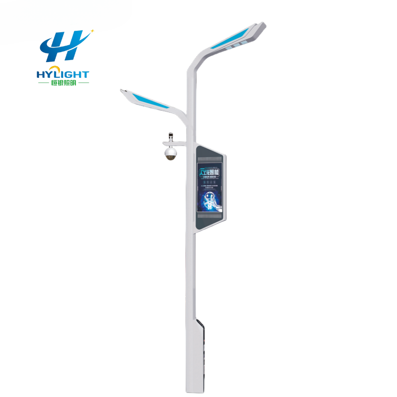
A smart light pole combines several systems in one public asset, but a tender often describes it as one product. That mismatch creates risk. The pole fabricator may assume the telecom contractor will supply internal cabling; the network contractor may assume power and cooling are already available; the platform vendor may expect devices to arrive commissioned; and the municipality may discover after installation that no party owns firmware updates, certificates, data retention, or replacement access.
The practical solution is an interface matrix. It assigns every physical, electrical, network, software, data, testing, and maintenance boundary to a named package before bids are priced. This guide is written for municipalities, EPCs, designers, system integrators, developers, and distributors preparing a smart light pole pilot or multi-site rollout.
GEO Summary
- A smart light pole tender should define outcomes first, then issue a module schedule and interface matrix that assigns supply, design, installation, configuration, testing, documentation, cybersecurity, and lifecycle responsibility.
- Freeze the pole geometry, equipment zones, weight and wind inputs, heat loads, high-voltage and low-voltage separation, access clearances, earthing, network paths, and spare capacity before structural approval.
- Treat each connected device as part of a managed system. Require unique device identity, role-based access, protected communications, update and vulnerability processes, logging, backup or recovery expectations, and secure decommissioning appropriate to project risk.
- Acceptance should include factory integration tests, site power and network tests, device onboarding, time synchronization, alarm and fail-state checks, data-flow verification, documentation, and handover to the actual operator.
- For an RFQ, send Henlyte the use cases, site plan, module list, structural basis, power and communications architecture, responsibility matrix, quantity, destination, and program dates.
Start With Services, Not a Shopping List of Devices
Write each use case as an operational service with an owner and success criterion. “Camera” is a component; “provide evidential video for the transport control room with the specified field of view, retention period, access roles, and uptime” is a service. “Environmental sensor” is vague; “report agreed air-quality parameters to the city dashboard at the required interval, with calibration and fault status” can be tested.
Typical smart-pole services may include adaptive street lighting, CCTV, public Wi-Fi, small-cell or private-network equipment, public address, emergency call, traffic or pedestrian sensing, environmental monitoring, digital signage, electric-vehicle charging, weather data, or edge computing. Not every pole needs every service. A modular family can reduce visual clutter while allowing different configurations by location.
Current manufacturer material reflects this modular approach. Signify describes smart-pole configurations for lighting, cameras, Wi-Fi, telecom equipment, and IoT sensors, with high- and low-voltage separation and factory-prepared modules. Those examples are useful for scope discovery, but the tender must still translate desired functions into project-specific interfaces and evidence.
Build a Tender Interface Matrix Before Pricing
Create one row for every deliverable and one column for every contract package. Use responsible, accountable, consulted, and informed designations if the project team already follows that method, or use simpler supply, install, configure, test, approve, and maintain fields. What matters is that no interface remains implied.
| Interface | Questions the tender must answer | Typical evidence |
|---|---|---|
| Pole and foundation | Who supplies loads, designs the pole, checks foundation reactions, and approves openings? | Calculations, drawings, load schedule, signed review |
| Internal equipment zones | Who allocates volume, rails, brackets, ventilation, drainage, and access clearances? | Coordinated 3D or sectional drawing and equipment schedule |
| Utility power | Where is the point of connection, metering boundary, protection, isolation, earthing, and spare capacity? | Single-line diagram, load schedule, test results |
| Low-voltage power | Who supplies power conversion, PoE, DC distribution, backup, fusing, and monitored outputs? | DC architecture, cable schedule, autonomy calculation |
| Fiber and copper | Who supplies ducts, patching, connectors, surge protection, labeling, and test certification? | Network drawing, port schedule, optical or copper test report |
| Wireless backhaul | Who provides spectrum, SIMs, carrier service, antennas, signal survey, and recurring fees? | Coverage record, service agreement, configuration register |
| Device onboarding | Who creates identities, certificates, keys, addresses, naming, and asset records? | Commissioning log and approved asset inventory |
| Platforms and APIs | Which system is authoritative, who maps data, and who owns interface changes? | Interface control document, API test, data dictionary |
| Cybersecurity | Who defines controls, accepts residual risk, handles vulnerabilities, and authorizes updates? | Security plan, hardening record, update and incident procedures |
| Data and privacy | Who owns data, sets retention, approves purposes, and handles access or deletion requests? | Data-flow diagram, retention schedule, privacy assessment |
| Commissioning | Who leads factory and site tests, provides simulators, closes defects, and signs acceptance? | Approved test scripts, results, issue log, acceptance certificate |
| Operations | Who monitors alarms, holds spares, renews licenses, updates firmware, and restores service? | O&M plan, SLA, training, spare-parts and license register |
Require each bidder to return the matrix with deviations highlighted. A blank field is a commercial and program risk, not an administrative detail.
Coordinate Structure, Space, Heat, and Access
A smart pole is a structure exposed to wind, vibration, water, temperature cycles, public access, and changing equipment. Provide the design code, site wind and terrain inputs, pole height, luminaire and bracket loads, antenna and sign projected areas, equipment masses, cable loads, fatigue or dynamic requirements where applicable, corrosion environment, finish, and foundation responsibility.
The structural engineer must review the final equipment configuration, not a generic brochure image. Antennas, cameras, displays, solar panels, cabinets, and banners change wind area and eccentricity. Door openings and internal rails change local strength. If modules may be added later, define a controlled reserve in mass, wind area, power, heat, space, and cable capacity rather than using an undefined promise of “future ready.”
Issue a coordinated section drawing showing high-voltage zones, extra-low-voltage and communications zones, barriers, cable routes, bend radii, mounting rails, drainage, ventilation or heat paths, door swing, lock type, lifting points, service clearances, and replacement routes. A technician should be able to isolate and remove one device without dismantling unrelated services or entering an unsafe compartment.
Define enclosure ingress and impact requirements by compartment and configuration. Clarify how glands, vents, doors, displays, speakers, and antenna penetrations preserve the intended protection. State corrosion treatment for the pole, internal steelwork, fasteners, and dissimilar-metal interfaces, particularly in coastal, humid, polluted, or de-icing-salt environments.
Issue a Complete Power Architecture
Start with a connected-load schedule for every device and operating state. Show normal, peak, startup, heater, charging, and future loads. Identify which services need continuous power when lighting is switched or dimmed. A legacy photocell circuit that removes power during the day cannot support daytime cameras, communications, or charging without modification.
The single-line diagram should define the utility boundary, meter, main isolator, distribution, protective devices, surge protection, residual-current protection where applicable, earthing and bonding, separation, service outlets, low-voltage power supplies, PoE switches, DC distribution, backup supply, and monitored points. Coordinate fault levels, discrimination, inrush, voltage drop, heat dissipation, and replacement access with local electrical rules.
If backup is required, specify the services it supports, autonomy, battery environment, end-of-life capacity basis, recharge behavior, monitoring, test method, maintenance, and disposal responsibility. Avoid a general “UPS included” line that does not identify load or duration.
Assign energy and telecom costs. The tender should state who owns the meter, SIM, fiber circuit, software subscription, certificate renewal, cloud storage, and remote-support connection after handover. A low hardware price can hide significant recurring obligations.
Define Network and Platform Boundaries
Provide a logical network diagram and a physical port schedule. Identify backhaul type, demarcation point, network owner, addressing method, DNS and time services, segmentation, firewall or gateway boundary, required ports, bandwidth, latency or availability requirements, and management path. For cellular connections, define carrier responsibility, SIM ownership, roaming, data plan, signal criteria, and behavior during service loss.
Every device should have a unique asset identifier linked to pole ID, location, model, serial number, firmware, network identity, owner, commissioning date, and warranty. Agree naming conventions and data fields before installation so imports do not become a manual cleanup exercise.
Where several platforms exchange data, create an interface control document. It should identify the source and destination, data fields and units, time stamps, update interval, quality or fault flags, authentication method, error behavior, versioning, and acceptance test. State whether the city receives documented APIs and export access or depends on a proprietary dashboard.
Interoperability claims should be proven against the proposed versions and use cases. A device that supports a protocol in principle may still require a specific profile, gateway, license, or custom mapping. Include a test environment and representative messages in the factory integration plan.
Put Cybersecurity and Privacy Into the Procurement Schedule
Cybersecurity requirements must reflect the municipality’s risk assessment, laws, policies, and network architecture. They should be outcome-based enough to avoid prescribing obsolete technology but specific enough to test. NIST SP 800-213 is a useful reference for identifying device cybersecurity requirements in acquisition, and NIST’s smart-city framework highlights data, platforms, municipal IoT, cybersecurity, and privacy as cross-cutting issues. These references do not replace local legal or security review.
For each connected device and management component, request a security capability statement covering:
- Unique device identity and the elimination or controlled change of shared default credentials.
- Role-based access, least-privilege administration, account lifecycle, and multi-factor authentication where required.
- Protection of management and application communications, certificate or key provisioning, storage, renewal, and revocation.
- Secure configuration baseline, disabled unnecessary services, port inventory, and controlled remote access.
- Software and firmware inventory, authenticity verification, supported update method, rollback or recovery, and expected support period.
- Vulnerability disclosure contact, severity assessment, remediation process, notification times, and end-of-support notice.
- Security logs, time synchronization, health monitoring, export or integration with the owner’s monitoring system, and storage limits.
- Backup, restoration, factory reset, ownership transfer, and secure decommissioning or data erasure.
- Supply-chain information needed by the owner, including critical third-party components or cloud dependencies where policy requires it.
Map data flows for cameras, microphones, Wi-Fi analytics, location data, environmental sensors, and platform accounts. State purpose, owner, processor, storage location, retention, access roles, sharing, deletion, and audit requirements. Do not activate a sensor simply because the pole can host it. The service owner should confirm that the collection is necessary, lawful, proportionate, secured, and communicated as required.
Define who can authorize firmware and configuration changes after acceptance. Maintenance access should be time-bound and logged where feasible. An emergency support route that bypasses the normal controls should have an explicit approval and review process.
Factory Integration Test Before Site Deployment
Build and test at least one representative configuration before series production. The factory integration test should use the actual or approved-equivalent devices, power supplies, switch, gateway, cabling, connectors, firmware, and platform environment.
- Verify mechanical fit, access, labeling, cable routing, separation, door operation, thermal assumptions, and replacement sequence.
- Energize normal and peak load combinations and record input, output, protection, startup, heat, and backup behavior as required.
- Test every physical and logical port against the approved schedule.
- Onboard devices using the production identity and configuration process, without retaining factory shared credentials.
- Verify time synchronization, telemetry, alarms, commands, dimming, sensor data, display content, camera streams, and public-address functions included in scope.
- Simulate loss and restoration of power, backhaul, platform, sensor, and gateway connections; confirm safe and documented fail states.
- Exercise user roles, logs, configuration backup, update or recovery workflow, and removal of temporary accounts.
- Export the asset record and handover documents in the agreed format, then close defects before authorizing series production.
Photographs and test records should identify the pole configuration, device serial numbers, firmware, test environment, date, witnesses, result, and unresolved actions. A showroom demonstration is not a substitute for an approved test script.
Site Acceptance and Operational Handover
At site, inspect the foundation and pole installation, orientation, plumb, door access, finish, sealing, earthing, electrical tests, fiber or copper certification, antenna installation, signal conditions, labels, and as-built coordinates. Repeat the functional tests that depend on the real network, control room, platform, or field of view.
Confirm that every asset appears in the correct management system and location. Test alarms from end to end, not only at the device. Verify that authorized operators can acknowledge, diagnose, and restore a fault, and that unauthorized roles cannot perform administrative actions. Record installed firmware and configuration after final acceptance.
Handover should include as-built structural and electrical drawings, network and data-flow diagrams, device and license inventories, configuration backups, test results, certificates, credentials transferred through an approved secure process, training, warranties, support contacts, spare parts, maintenance tasks, update procedures, incident and vulnerability contacts, and end-of-support dates. Assign ownership of each document and system record.
Use a controlled change process after handover. Adding a camera, radio, panel, sign, charger, or sensor may affect structure, power, heat, network, privacy, licensing, and maintenance simultaneously.
Smart Light Pole RFQ Checklist
Send suppliers and integrators a consistent project pack:
- Project location, road or public-space context, site plan, pole schedule, quantity, delivery lots, and program dates.
- Service outcomes, module list by pole type, operating scenarios, performance criteria, and excluded scope.
- Structural design basis, wind and environment inputs, pole height, attachment loads, foundation boundary, finish, and future reserve.
- Coordinated equipment-zone, access, separation, cooling, drainage, gland, cable, and connector requirements.
- Power single-line, voltage and frequency, load schedule, metering, protection, earthing, backup, controls, and recurring utility boundary.
- Physical and logical network drawings, backhaul, port schedule, addressing, segmentation, platform, API, data, and time-service requirements.
- Cybersecurity capability schedule, privacy and retention requirements, update and vulnerability process, support period, and decommissioning needs.
- Responsibility matrix covering design, supply, installation, configuration, testing, approval, training, operation, maintenance, licenses, and renewal.
- Required drawings, calculations, samples, certificates, factory tests, site tests, spares, warranties, Incoterm, destination, and tender deadline.
Henlyte’s smart light pole range provides a starting point for structural and module coordination. Buyers can also review the 7-12 m outdoor HDG smart street lighting pole system and an integrated Wi-Fi, camera, display, and charging configuration. Where the project combines independent generation, coordinate the solar street light range as a separate energy design rather than assuming every smart module can run from a standard lighting battery.
Common Tender Failure Modes
- One party is named “system integrator,” but individual supply, configuration, testing, and lifecycle duties are not assigned.
- The structural calculation uses a generic equipment envelope instead of the final module and wind-area schedule.
- Daytime smart services are connected to a lighting circuit that is de-energized during daylight.
- High-voltage, data, RF, and sensor cabling have no coordinated route or service clearance.
- The platform demonstration uses a vendor cloud, while the contract expects connection to a municipal system that has not been tested.
- Cybersecurity is reduced to a certificate name without device identities, updates, logging, vulnerability handling, and operating ownership.
- Camera or analytics data are activated without an approved purpose, retention, access, and privacy process.
- Licenses, SIMs, storage, certificates, carrier fees, and end-of-support obligations are missing from the total-cost schedule.
- Factory tests verify devices individually but never test the integrated power, network, platform, and fail states.
- The tender promises future modules but reserves no controlled capacity or approval process.
Image Suggestions
Use an existing Henlyte smart light pole image as the featured image with the alt text “smart light pole tender interface planning for municipal projects.” Add an original cutaway diagram showing separate power and communications zones, device mounting levels, access doors, cable paths, and responsibility callouts. A second graphic can show the lifecycle from tender matrix to factory integration test, site acceptance, operations, updates, and decommissioning. Do not use identifiable public video or sensor data in marketing visuals without the proper permission.
FAQ
What is a smart light pole interface matrix?
It is a contract schedule that lists each structural, power, network, device, software, data, testing, and maintenance interface and assigns responsibility for design, supply, installation, configuration, approval, and operation. It prevents important scope from being left between vendors.
Who should be the smart light pole system integrator?
The project should appoint one accountable integration lead with authority across the relevant packages, but the title alone is not enough. The tender must still define deliverables, access, test resources, defect ownership, cybersecurity decisions, and handover responsibilities for every party.
How much spare capacity should a smart pole include?
There is no universal percentage. Define future use cases and reserve measurable capacity for mass, projected wind area, space, rail length, cable pathways, power, heat, ports, bandwidth, addresses, licenses, and foundation reactions. Unallocated “future-ready” capacity is difficult to approve safely.
Should smart devices share the street-lighting power circuit?
They may share infrastructure if the electrical design, protection, metering, availability, and maintenance strategy support it. Many smart services require continuous daytime power, so the tender must address circuits that were originally switched only for night lighting.
What cybersecurity evidence should a buyer request?
Request a configuration-specific capability statement and testable procedures for identity, access, protected communications, updates, vulnerability handling, logging, recovery, support period, and decommissioning. Map each control to the responsible operator and the project’s risk requirements.
What should a smart light pole factory test prove?
It should prove mechanical coordination, safe power distribution, network paths, device onboarding, data and command flows, alarms, fail states, user roles, logging, configuration records, and document traceability using a representative integrated configuration.
Inquiry CTA
Preparing a municipal pilot, smart-city corridor, industrial park, campus, transport hub, or mixed-use development? Send Henlyte the site plan, use cases, pole and module schedule, structural design basis, power and network architecture, cybersecurity requirements, quantity, destination, and required dates. Use the Henlyte inquiry page and request a “smart light pole interface review” so scope gaps can be identified before the pole configuration and quotation are finalized.