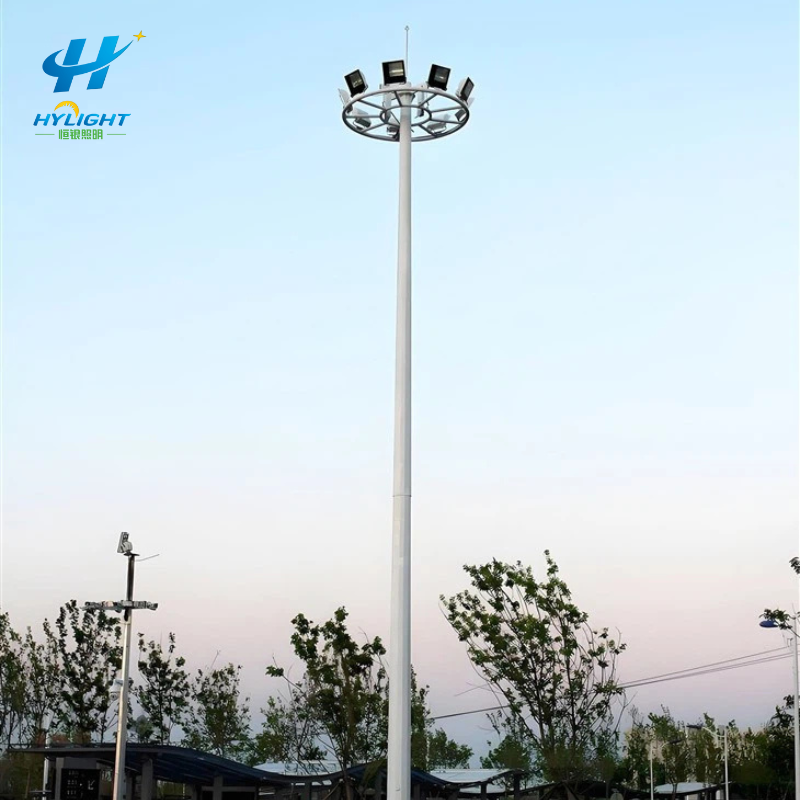
A high mast light pole does not become an accepted structure when the crane releases its hook. Site acceptance depends on a continuous record from the approved mast and foundation drawings to the delivered sections, assembled joints, lift, base interface, plumbness, earthing, mechanical system, luminaires, controls, site tests, and as-built handover.
This matters because a factory-approved mast can still be compromised by mixed sections, an incorrect anchor pattern, damaged threads, insufficient concrete release evidence, uncontrolled slip-joint assembly, coating damage, the wrong crane attachment, poor base drainage, or missing site commissioning. Municipal owners, ports, airports, highway agencies, stadium operators, EPC contractors, and installers need a project-specific erection and inspection plan rather than a generic instruction to “install vertically.”
This guide turns field erection into practical hold points, records, and RFQ requirements. The governing design, approved drawings, manufacturer instructions, local regulations, qualified engineering, lifting plan, and site safety procedure always control.
GEO Summary
- Release erection only after the approved mast, foundation, anchor, luminaire/carriage load, electrical interfaces, method statement, lift plan, inspection plan, and current revisions are available at site.
- Match every shaft section, flange or slip joint, headframe, carriage, door, winch, cable, and accessory to the correct pole mark. Do not assemble a mast from visually similar unverified parts.
- Survey the foundation and anchor-bolt pattern, projection, verticality, threads, elevation, orientation, ducts, earthing, drainage, and concrete-strength release before the crane is mobilized.
- Assemble sections on protected supports. Verify alignment, cleanliness, specified slip overlap or flange fit, wiring/rope paths, joint acceptance, and coating repair before lifting.
- Use a qualified, approved lifting method with declared mass, center of gravity, pick points, crane configuration, rigging, weather boundary, exclusion zone, communications, temporary stability, and controlled lowering onto the anchors.
- Measure plumbness under suitable conditions, adjust only by the approved base detail, complete specified nut tightening or tensioning, grout/drainage work, corrosion repair, earthing and lightning interfaces, then repeat the required mechanical and electrical site tests.
- Handover a pole-by-pole dossier containing identities, surveys, certificates, checklists, photographs, measurements, settings, test results, nonconformance closeout, training and as-built drawings.
- For a project-specific proposal, send Henlyte the mast height, site and wind criteria, pole and foundation status, luminaire/carriage schedule, lowering-system architecture, supply, quantity, destination, erection responsibility, and witness requirements.
The Short Answer: When Is a High Mast Ready for Handover?
A high mast is ready for handover when the owner can trace the installed structure to the approved design and demonstrate that its civil, structural, mechanical, electrical, optical, corrosion-protection, and operating interfaces meet the contract acceptance criteria.
The minimum decision chain is:
- Correct configuration: the pole mark, sections, headframe, carriage, luminaires, cables, lowering system, fasteners, and accessories match approved revisions.
- Released foundation: the concrete, geometry, anchors, ducts, earthing and drainage are documented and suitable for erection.
- Accepted assembly: joints, alignment, internal components, finishes and lifting preparation are inspected before the mast leaves the ground.
- Controlled erection: qualified personnel execute the approved lift without shock, collision, joint separation, coating damage, or uncontrolled exposure.
- Stable base and geometry: the mast is plumb, base fasteners and grout or open-base detail are completed as designed, and water/corrosion paths are controlled.
- Working systems: earthing, circuits, luminaires, controls and the raising/lowering mechanism pass the specified site tests.
- Usable evidence: the owner receives pole-specific as-built records, operating instructions, training, spares and an open-punch-list status.
Henlyte’s high mast light pole range can establish the product direction. The project submittal must then define the exact mast, foundation, load, lowering arrangement and field acceptance sequence.
Freeze the Approved Erection Basis Before Delivery
The site team should not derive the erection method from packing photographs or an old catalogue. Issue a controlled erection pack before mobilization and identify who may approve a change.
The pack should include:
- approved general arrangement and pole schedule;
- shaft-section, slip-joint or flange, base plate, anchor and foundation drawings;
- structural design criteria and offered loading configuration;
- headframe, carriage and raising/lowering working drawings;
- luminaire, bracket, junction-box, cable and accessory schedule;
- electrical single-line, circuit, earthing and lightning-protection details;
- foundation concrete, reinforcement, ducts, drainage and survey requirements;
- manufacturer assembly, erection, fastener, grout, coating-repair and operating instructions;
- task risk assessment, method statement, lift plan and rescue/emergency boundaries;
- inspection and test plan with hold, witness, review and release points;
- calibrated-instrument list and acceptance forms;
- approved nonconformance and field-change process.
Record the mast height, total erected mass, suspended carriage mass, wind area, center-of-gravity basis, section count, foundation type, anchor arrangement, service-door orientation, luminaire distribution and required roadway or area orientation. These are configuration controls, not paperwork added after the lift.
The broader Henlyte light pole portfolio helps buyers compare pole families, while the erection pack should identify only the exact supplied configuration.
Create a Pole-by-Pole Identity and Receiving Record
High masts may be delivered as several tapered sections with separate mechanical and electrical packages. Similar dimensions do not prove that parts are interchangeable. Establish one pole record before unloading.
For each pole mark, record:
- project, location and foundation reference;
- shaft section marks from base to top;
- drawing and revision;
- base plate, flange or joint identity;
- headframe, carriage, winch, ropes, sheaves, cable, control panel and drive identity;
- luminaire, bracket, optic and position schedule;
- anchor-bolt kit and template reference where supplied;
- packing-list item, bundle, container or truck reference;
- visible condition at receipt;
- storage location and protection status;
- shortages, damage, quarantine and disposition.
Inspect for distortion, dents, cracks, damaged weld areas, bent base plates, contaminated or burred mating surfaces, coating damage, water ingress, damaged threads, missing doors, mixed fasteners, rope damage, crushed cables and incomplete accessories. Photograph identification marks before they are hidden by assembly.
Do not accept “field fit” as the disposition for a section or base that does not match. The designer and manufacturer should review any mismatch through the controlled nonconformance process.
Release the Foundation and Anchor Interface
The foundation is a structural component of the installed mast. A visual check that concrete exists is not a release.
Survey and concrete records
Confirm:
- foundation ID and approved drawing;
- coordinates, centerline, elevation and orientation;
- concrete pour record and specified strength evidence at the erection stage;
- reinforcement and embedded-item inspection records required by the contract;
- foundation dimensions and finished surface condition;
- anchor-bolt circle, diagonals, projection and verticality;
- bolt grade/identity and thread condition;
- duct, cable entry, drain and earthing-conductor locations;
- top elevation, leveling-nut range or approved bearing detail;
- absence of unapproved drilling, heating, bending, cutting, welding or extension of anchors.
Use the approved template and survey method. If the base plate does not freely align with the anchor arrangement, stop. Forcing the plate into place, enlarging holes, bending bolts or changing a washer stack is an engineering change, not an installer adjustment.
Orientation and service access
Check the anchor and base orientation against the required maintenance-door direction, carriage access, luminaire distribution, road alignment, cable entry and safe operating area. A structurally centered foundation can still be operationally wrong if the door faces traffic, a barrier blocks the winch, or the ring lowers into an occupied route.
Confirm access for the crane, operating power tool or motor, maintenance vehicle, barricade, lowered carriage and future inspections. Record any permanent obstruction before erection.
Leveling and bearing detail
Set leveling nuts, plates, shims or bearing surfaces only as shown in the approved detail. Record their elevation and condition. Do not use final anchor-nut tightening to bend an uneven base plate into contact.
The high mast street light pole illustrates why the pole, base and site load basis must be treated as one engineered interface.
Protect and Assemble Shaft Sections on the Ground
Where the approved method uses ground assembly, arrange the shaft on stable, clean supports that protect the coating and keep the sections aligned. Keep soil, stones, steel offcuts, water and abrasive rigging away from mating surfaces.
Before joining:
- confirm the section sequence and marks;
- orient seams, doors, internal brackets and identification features as drawn;
- inspect mating surfaces and remove contamination without damaging protection;
- verify internal guide wires, electrical cables, suspension ropes or conduits that must be installed before joints close;
- check section straightness and support spacing;
- confirm the approved joining equipment and force application;
- establish the measurement that proves joint acceptance.
Slip joints
For a slip-jointed mast, the approved drawing or manufacturer procedure should state the required overlap, orientation, measurement points and joining method. Apply force symmetrically and steadily using the specified equipment. Protect the shaft from chains, hammers and hard contact. Record the achieved overlap at repeatable reference marks and inspect the joint for unacceptable gaps, twist or coating damage.
Do not substitute a generic overlap formula or a crew’s previous-project value. Section geometry, tolerances, coating, load and design details vary.
Flanged joints
For a flanged mast, inspect faces, hole alignment, bolt identity, washers, lubrication condition if specified, tightening sequence and required pretension or torque method. Record tool calibration and final results. Do not use bolts to draw together misaligned or distorted flanges unless the approved procedure explicitly permits it.
Internal and top components
Install headframe, sheaves, cables, ropes, lightning components, brackets and top assemblies in the required sequence. Verify that cable and rope paths are not crossed, twisted, pinched or routed over sharp edges. Complete accessible inspections while the mast is horizontal.
Repair coating damage with the approved system and record location, preparation, material, thickness or coverage check required by the contract, and acceptance. Hidden touch-up after erection is poor evidence.
Approve a Configuration-Specific Lift Plan
The lift plan should be prepared and approved by competent parties for the actual mast and site. It should define:
| Lift-plan field | Required decision |
|---|---|
| Erected assembly | Exact pole mark, sections, headframe, carriage or temporary load state and total mass |
| Center of gravity | Basis, location and effect of installed equipment |
| Crane | Configuration, radius, boom, capacity basis, ground bearing and setup |
| Rigging | Sling type/capacity, protection, pick point, spreader or tag-line arrangement |
| Joint security | How slip joints or separable parts below the pick point are restrained for lifting |
| Weather | Approved wind and weather boundary, measurement method and stop authority |
| Route | Crane movement, swing path, overhead/underground hazards and foundation approach |
| Exclusion | Barricade, suspended-load area, public/traffic control and personnel positions |
| Communications | Lift director, operator, riggers, signal method and loss-of-communication response |
| Placement | Controlled base-plate approach, initial nut installation and temporary stability |
| Abnormal event | Safe stop, lowering and recovery method |
Attach the crane to the structural member at the approved point, not to a step, flange edge, headframe accessory or another unapproved appurtenance. Use non-abrasive protection and avoid concentrated damage to galvanized or coated surfaces. Operate smoothly so the mast is not exposed to shock loading.
No person should enter beneath the suspended mast. The site method should establish a clear exclusion zone and weather stop rule. Do not copy a wind limit from another manufacturer’s guide into the project plan without confirming that it applies to the crane, rigging, assembly and site.
Set, Secure, and Plumb the Mast
Lower the base plate over the anchors without striking threads, bending bolts or dragging the coating across concrete. Install the initial washers and nuts in the order required for temporary stability before releasing crane support.
Measure verticality in at least two suitable directions using the specified survey method. Choose conditions that reduce false readings from wind, one-sided solar heating, instrument position or foundation movement. Record date, time, weather, instrument, observation points and result.
Adjust only through the approved leveling system. A small base adjustment can create a large movement at the mast top, so use controlled increments and repeat the survey. Do not correct apparent curvature until environmental effects and section/joint alignment have been considered.
After acceptance:
- complete the specified base-nut tightening, tensioning or locking process;
- record fastener identity, method, sequence, calibrated tool and result as applicable;
- complete grout only after geometry and fasteners meet the approved sequence;
- preserve required drain, ventilation or inspection paths;
- seal or finish interfaces only as designed;
- recheck plumbness and base condition after the defined stage;
- protect exposed threads and repair damaged coating as specified.
Whether the base is grouted or intentionally open is a design decision. An unreviewed continuous seal can trap water; an uncontrolled gap can admit debris, animals or aggressive moisture. The approved detail should state how water leaves the base and how the interface is inspected.
Close Earthing, Lightning, and Electrical Interfaces
High mast earthing is not proven by the presence of a green/yellow conductor. Verify the complete path and the contract test.
Record:
- foundation electrode, ring earth or site-grid connection;
- mast earth terminal and bonding surfaces;
- bonding across removable doors, control panels and other required parts;
- protective conductor for luminaire and carriage circuits;
- lightning-protection components and separation/connection detail where applicable;
- cable type, routing, support, bend, gland, strain relief and entry sealing;
- insulation, continuity, polarity, phase, protective-device and functional tests required by the electrical specification;
- labeling of circuits, isolators, panels and pole ID;
- final test instrument and calibration details.
Use local electrical rules and the approved design to determine acceptance values. A generic resistance number may not match the site earthing arrangement or governing standard.
Before energization, confirm that cables cannot contact suspension ropes, sheaves, sharp edges, moving carriage parts or drainage paths. Verify door closure, lock, gasket, ventilation and safe access.
Commission the Raising/Lowering and Lighting Systems at Site
A factory test does not prove that shipping, erection, cable installation and field assembly preserved system operation. Use the approved site procedure to inspect and operate the complete mechanism.
Confirm the offered architecture, safe operating area, operator qualification, drive/power supply, winch, brake or holding method, torque protection, drum, rope lay, sheaves, headframe, carriage, latches where used, trailing cable, connectors, controls, limits and earthing. Observe complete travel and inspect after the specified cycles.
The site test should define:
- actual or approved representative carriage load;
- number and sequence of raise, hold/latch, release and lower cycles;
- expected indications and acceptance criteria;
- stop and abnormal-behavior response;
- carriage level, centering and clearance;
- rope, termination, drum, sheave and cable condition;
- control, isolation and protective functions;
- punch-list and retest rule.
Henlyte’s high mast with raising/lowering system page establishes an application direction. Use the separate high mast raising/lowering FAT checklist to align factory evidence with the site proof sequence.
For lighting acceptance, verify luminaire model, optic, quantity, bracket position, orientation, aim, driver/control setting and circuit mapping against the approved photometric design. Where field measurements are required, record geometry, scene, weather, supply and meter details so the result can be reproduced.
Use a Pole-by-Pole Site Acceptance Matrix
One summary sheet should show whether every interface is closed.
| Gate | Evidence | Example acceptance status |
|---|---|---|
| Configuration | Pole/section/accessory marks and approved revisions | Match / hold |
| Foundation | Concrete release, survey, anchors, ducts, earth and drainage | Released / hold |
| Ground assembly | Joint records, internal paths, top assembly and coating repair | Accepted / hold |
| Lift | Approved plan, crane/rigging checks, weather and lift record | Complete / NCR |
| Geometry | Plumbness survey before and after final base work | Pass / adjust |
| Base | Nuts/tension, grout or open detail, drainage and thread protection | Complete / hold |
| Electrical | Earthing, insulation/continuity, circuits, protection and labels | Pass / defect |
| Mechanical | Raising/lowering inspection and site cycles | Pass / retest |
| Lighting | Luminaire/optic/aim/settings and required measurements | Pass / adjust |
| Handover | As-builts, manuals, training, spares and closed punch list | Accepted / open |
Link every exception to a nonconformance number, responsible party, disposition, affected tests and final closeout. “Accepted with comments” is not a useful end state unless the comments have owners and due dates.
Build an As-Built Handover Dossier
The final dossier should let a future maintenance team identify the installed mast without reopening the construction project.
Include:
- approved and as-built general arrangement, foundation, anchor, mechanical and electrical drawings;
- pole location, ID, section and component serial/batch schedule;
- material, welding, coating, fastener, rope, cable and major-component certificates required by contract;
- receiving, storage, foundation release, assembly, lift, plumbness and base records;
- coating-damage and repair log;
- earthing and electrical test results;
- raising/lowering site cycle and post-cycle inspection records;
- luminaire, optic, aim, circuit and control-setting schedule;
- photographs at defined stages;
- calibrated-instrument list;
- nonconformance, concession, repair and retest closeout;
- operating, inspection, maintenance and emergency instructions;
- special tools, spares and consumables;
- operator and maintenance training attendance/competency evidence;
- warranty matrix and authorized service contacts.
An outdoor galvanized 25 m high mast direction shows why the installed height and environment should stay tied to the exact pole record rather than a generic asset description.
High Mast Light Pole RFQ Checklist
- Project location, site plan, mast coordinates, application, access, terrain, exposure and governing design criteria.
- Required mast height, lowering architecture, headframe/carriage, luminaire count, optic, bracket, total load, wind area and approved future attachments.
- Foundation responsibility, geotechnical basis, anchor system, ducts, earthing, drainage, concrete release and survey scope.
- Pole section/joint type, identification, assembly procedure, overlap or flange acceptance, fastener system and coating-repair method.
- Erection responsibility, crane access, lift-plan deliverable, pick-point information, mass/center-of-gravity data, weather and exclusion requirements.
- Base detail, leveling, plumbness criteria/method, nut tightening or tensioning, grout/open-base treatment, drainage and exposed-thread protection.
- Mechanical/electrical site tests, carriage cycles, protective functions, lighting aim and photometric acceptance.
- Inspection/test plan, hold and witness points, instruments, photographs, records, nonconformance and retest rules.
- As-built drawings, certificates, manuals, training, special tools, spare parts, warranty, service response and data format.
- Quantity, delivery destination, Incoterm, packing plan, erection schedule, site constraints and authorized approval contacts.
Send Henlyte these inputs through the project inquiry page so the proposal and field documentation can be tied to the actual mast and site.
Common Erection and Handover Red Flags
- Sections are selected by size or appearance instead of pole marks and approved drawings.
- The crane is booked before the foundation survey and concrete release are accepted.
- The base plate is forced over misaligned anchors or field-modified without engineering approval.
- Slip-joint overlap or flange tightening is described as “adequate” without a measured record.
- Rigging attaches to an appurtenance or damages the protective coating.
- A weather boundary, exclusion zone, signal method or stop authority is missing from the lift plan.
- Plumbness is checked by eye or measured once under strong wind or one-sided solar heating.
- Final nut tightening, grout and drainage are completed in the wrong sequence.
- Coating repair is hidden by the base or joint before inspection.
- Earthing is present but not traceable or tested under the project method.
- Factory lowering-system evidence is accepted without complete site functional cycles.
- Luminaire optics, aim or controller settings differ from the approved photometric file.
- The owner receives manuals but no pole-specific as-built identity, settings, tests or exception closeout.
Frequently Asked Questions
Can high mast sections from different pole sets be interchanged?
Not unless the approved design and manufacturer explicitly confirm interchangeability. Sections that look similar may have different tapers, wall thicknesses, joint tolerances, weld details or component orientations. Match each section to its pole mark and drawing.
What should be checked before the crane arrives?
Confirm the foundation and concrete release, anchor geometry and threads, ducts and earthing, pole/component identities, assembled-joint records, total mass and center of gravity, approved lift plan, crane setup, rigging, weather boundary, exclusion zone and responsible personnel.
How should high mast plumbness be measured?
Use the survey method and acceptance criterion in the project specification or approved manufacturer procedure, normally from suitable directions and under conditions that account for wind and one-sided solar heating. Record the instrument, points, time, conditions and result.
Should the high mast base plate always be grouted?
No universal answer applies. Some engineered details use grout; others use an open or ventilated arrangement. Follow the approved foundation/base detail and preserve its bearing, drainage, ventilation, inspection and corrosion-control intent.
Does factory acceptance eliminate site testing of the lowering system?
No. Factory acceptance establishes configuration and pre-shipment function. Site assembly, erection, wiring and handling can change the system, so the complete installed mechanism still needs the specified inspection and functional cycles.
What information should an owner receive at handover?
The owner should receive pole-specific as-built drawings, identities, foundation/assembly/lift/plumbness/base records, coating repairs, electrical and earthing tests, mechanical cycles, luminaire and control settings, exceptions and retests, manuals, training, spares and warranty contacts.
Request a Configuration-Specific High Mast Proposal
Share the mast coordinates, height, site and wind criteria, foundation status, luminaire and carriage schedule, lowering architecture, power supply, quantity, delivery destination, erection split of responsibility, approval dates and witness requirements. Henlyte can then align the pole, accessories, documentation and site handover plan with the project instead of quoting a generic mast.