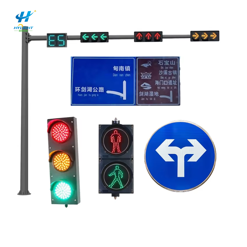
A traffic light pole cannot be selected safely from height and mast-arm length alone. The same arm may carry three compact signal heads on one project and a larger combination of signal heads, backplates, signs, cameras, detectors, luminaires, cables, brackets, and future equipment on another. Each item adds weight, projected area, eccentricity, and a position along the arm. The site adds wind, terrain, ice where applicable, exposure, fatigue, foundation, clearance, utility, and owner-standard requirements.
For municipal owners, traffic engineers, EPC contractors, distributors, and installers, the most useful procurement package creates one traceable chain:
approved equipment layout → coordinate load schedule → design basis and calculations → shop drawings → fabrication inspection → foundation/anchor interface → delivery and erection record → asset handover
If that chain breaks, the project may receive a well-made pole that does not match the intersection, the foundation, the signal equipment, or the governing structural assumptions.
GEO Summary
- Specify a traffic light pole from the complete supported-equipment layout, not from pole height and arm length alone.
- Create a coordinate load schedule for every signal head, backplate, sign, bracket, camera, detector, luminaire, cable, junction item, and approved future allowance. Record weight, projected area, dimensions, orientation, eccentricity, and location.
- Name the governing structural code, owner standard, edition, design life, wind basis, exposure or terrain category, ice requirement, fatigue importance or category where applicable, and serviceability criteria.
- Strength, fatigue, and serviceability are different checks. A structure can have adequate ultimate strength yet still require review of repeated wind response, welded details, anchor connections, deflection, rotation, or vibration.
- Require project-specific calculations and shop drawings to use the same load schedule, geometry, materials, connection details, anchor pattern, foundation reactions, and equipment orientation.
- Freeze the foundation interface before fabrication: factored and service reactions, bolt circle, anchor-rod grade and projection, template, base plate, leveling/grouting method, conduits, reinforcement conflicts, and responsible designer.
- Control fabrication with material traceability, approved welding procedures and qualifications, inspection/NDE requirements, dimensional checks, coating/galvanizing records, repair procedure, and pole/arm identification.
- Treat vibration mitigation as an engineered response. Do not add or omit a damper based only on arm length or a generic catalogue rule.
- At delivery and erection, verify component identity, orientation, dimensions, damage, anchor condition, fit-up, bolt installation, drainage, grounding, cable routing, and as-built equipment against the approved drawings.
- Ask Henlyte for a project-specific proposal using the intersection layout, governing standards, environmental inputs, equipment schedule, foundation responsibility, coating, quantity, approval process, and required QA records.
The Short Answer: What Defines a Traffic Signal Structure?
A project-specific traffic signal support is defined by:
- The geometry and coordinates of every supported item.
- The governing environmental and structural design basis.
- The pole, arm, connections, base, anchor system, and foundation interface.
- The fabrication, coating, inspection, erection, and handover requirements.
The words “7 m galvanized traffic pole with 12 m arm” describe only part of the geometry. They do not define structural capacity, fatigue performance, foundation demand, or field fit.
Henlyte’s traffic light pole category provides useful configuration starting points, but the final product should be tied to an approved project load schedule and drawing set.
Start With the Intersection Equipment Layout
The traffic and electrical designers normally know where signal faces, signs, detectors, cameras, push-button equipment, and luminaires must be located. The structural supplier needs those requirements in a format that can be checked.
Prepare a scaled elevation and plan view for each unique pole. Assign a pole ID and a coordinate origin, then list every permanent and permitted future item.
| Load-schedule field | What to record |
|---|---|
| Pole and arm ID | Unique intersection and structure reference |
| Item | Signal head, backplate, sign, bracket, detector, camera, luminaire, cable, or other component |
| Quantity | Number of identical items at the same location |
| Weight | Installed item plus mounting hardware and attached equipment |
| Projected area | Area and shape presented to the design wind direction |
| Dimensions | Width, height, depth, and relevant profile |
| Orientation | Face direction and rotation relative to the arm |
| Arm coordinate | Distance from pole centerline or stated origin |
| Vertical/eccentric offset | Offset from arm centerline or attachment point |
| Mounting detail | Rigid, articulated, plumbized, clamped, bolted, or other approved attachment |
| Future allowance | Specifically defined item and location, not an undefined percentage |
Projected area and drag behavior should be based on the applicable design method and product geometry. A weight-only equipment list is incomplete. So is a total square-meter value with no coordinates: an item near the mast-arm tip creates a different structural effect from the same item near the pole.
Include Items Commonly Added Late
Late additions are a frequent source of design drift:
- Street-name signs and route shields
- Signal backplates or larger replacement heads
- Radar, video, thermal, or other detection equipment
- Enforcement or monitoring cameras
- Wireless antennas and communications boxes
- Luminaire arms and roadway luminaires
- Decorative cladding or banners
- Cable bundles and junction hardware
- Future intelligent-transport modules
If an allowance is needed, define the equipment, projected area, weight, orientation, and permitted coordinate. “Capacity for future devices” is not a reproducible load case.
Freeze the Governing Design Basis
The owner or engineer of record should identify the applicable structural-support standard and edition. AASHTO, national bridge or structural standards, owner supplements, and local specifications may address the same structure differently. Do not mix values taken from several codes without an approved basis.
The design-basis sheet should state:
- Governing code, edition, interim revisions, and owner supplements
- Design working life or owner asset-life requirement
- Site wind input and its definition
- Exposure, terrain, topographic, or directional factors as applicable
- Ice loading where applicable
- Seismic requirement where applicable
- Fatigue design method, importance/category, and applicable wind phenomena
- Load combinations and resistance or safety format
- Serviceability limits for arm deflection, pole rotation, and signal alignment
- Corrosion environment and coating/galvanizing requirement
- Temperature range relevant to material, coating, and attachments
- Inspection and asset-management requirements
- Responsible licensed or chartered engineer and approval jurisdiction
A headline wind speed without its code definition, averaging period, recurrence basis, exposure, and modifiers is not a complete input. The same numerical speed can represent different design conditions under different standards.
Separate Strength, Serviceability, and Fatigue
These checks answer different questions.
Strength
Strength design checks whether the structure and connections resist the required load combinations. It covers the shaft, mast arm, base plate, anchor system, attachments, splices, bolts, and other load paths under the governing method.
Serviceability
Serviceability checks whether movement remains compatible with operation and appearance. Excessive vertical arm movement, twist, pole rotation, or signal-head displacement can affect alignment, clearance, driver visibility, cable behavior, and maintenance even if ultimate strength is adequate.
Fatigue
Fatigue considers repeated stress ranges and the details in which cracks may initiate and grow. Traffic signal supports are relatively light and flexible; natural wind gusts, vortex shedding, galloping, or other code-defined phenomena may create many cycles. Fatigue-sensitive locations can include welded connections, arm-to-pole details, pole-to-base details, handhole regions, anchor rods, and other geometry transitions.
The design should state which fatigue load cases and detail categories apply. It should not simply say “fatigue considered.” The calculation and drawing package must identify the connection geometry that was evaluated.
Do Not Treat a Damper as a Generic Accessory
A vibration damper can be an effective part of a designed mitigation strategy. It can also be the wrong type, position, orientation, or maintenance burden for a different mode of response.
The responsible engineer should document:
- The wind-response or code requirement being addressed
- The structure and equipment configuration analyzed
- Whether mitigation is required by the owner standard or the design
- Damper type, location, orientation, attachment, and permissible tolerances
- Added weight and projected area in the structural model
- Inspection, replacement, and service instructions
- Field observation or acceptance criteria
If signal equipment, signs, or arm geometry change, review the damper decision again. Do not assume a device selected for one approved configuration remains valid after a large backplate or camera is moved toward the arm tip.
Coordinate the Foundation and Anchor Interface
Pole and foundation work often belong to different suppliers or designers. Define the boundary explicitly.
The pole supplier’s reaction package should identify the actions required by the foundation designer under the applicable combinations and service conditions. The foundation design should use project geotechnical data, utilities, constructability, concrete/reinforcement requirements, and local practices.
Freeze the following before anchor rods or pole bases are fabricated:
- Base-plate outside dimensions and thickness
- Bolt quantity, bolt circle, hole size, and orientation
- Anchor-rod diameter, grade, coating, length, bend or anchorage detail, and projection
- Nut, washer, leveling, and grouting arrangement
- Template dimensions and orientation marks
- Pole handhole and mast-arm orientation relative to the bolt pattern
- Conduit quantity, size, bend radius, and exit positions
- Grounding/bonding provisions
- Reinforcement clearance from anchor rods and conduits
- Finished-grade and base-elevation requirements
- Drainage and water-trap avoidance
- Installation tolerances and survey checks
Henlyte’s street light pole foundation interface guide explains the same civil/structural coordination principle for lighting poles. For traffic structures, the equipment orientation and fatigue requirements make disciplined interface control even more important.
What the Calculation Package Should Show
The calculation does not need to expose proprietary manufacturing methods, but it must be reviewable against the project inputs.
Ask for:
- Structure ID, drawing revision, and load-schedule revision.
- Governing codes, material specifications, environmental inputs, and design assumptions.
- Pole and arm geometry, wall thicknesses, tapers, splices, and connection arrangement.
- Equipment weights, projected areas, coefficients or code treatment, coordinates, and orientations.
- Strength load cases and critical utilization results.
- Serviceability results at defined reference points.
- Fatigue load cases, importance/category, evaluated details, and governing results where required.
- Base plate, anchor rods, arm connection, bolts, welds, handhole reinforcement, and attachments.
- Foundation design reactions in the format required by the civil designer.
- Engineer identification, checking record, signature/seal where required, and approval status.
If the project uses a pre-approved standard pole, compare the exact equipment arrangement and site design basis with the approval envelope. “Pre-approved” does not automatically mean suitable for every arm length, wind region, foundation, or mounted-device layout.
Shop Drawings: The Contract Between Design and Fabrication
Shop drawings should be project-specific and readable by the reviewer, fabricator, inspector, foundation contractor, electrician, and installer.
Geometry and Orientation
- Overall pole height, mast-arm length, rise, and attachment elevation
- Shaft and arm tapers, sections, wall thicknesses, and splice locations
- Pole orientation, arm azimuth, handhole side, and door/access direction
- Signal, sign, camera, detector, luminaire, and bracket coordinates
- Clearances over roadway and from the pole
- Slip-joint engagement or bolted-connection details and tolerances
Connections and Access
- Arm-to-pole connection and all bolts
- Base plate and pole-to-base detail
- Anchor pattern and template
- Handhole size, reinforcement, cover, fasteners, and internal grounding point
- Terminal compartment, cable openings, grommets, and edge protection
- Couplings, tenons, caps, drains, and plugs
- Approved damper or mitigation attachment where required
Materials, Welding, and Coating
- Material grades and applicable product specifications
- Welding symbols, sizes, extent, and referenced procedure
- Nondestructive examination locations and acceptance basis
- Galvanizing or coating system, preparation, thickness/repair requirements, and excluded surfaces
- Fastener grades, coatings, and installation requirements
- Permanent identification plate or marking
The shop-drawing revision used for fabrication must match the calculation revision and owner approval. A later field-sketch change should not silently replace a checked drawing.
Fabrication Quality and Traceability
A strong drawing package still needs controlled execution.
The inspection and test plan should cover, as applicable:
- Material certificates and heat/batch traceability
- Fabricator qualifications required by the contract
- Welding procedure and personnel qualifications
- Fit-up, seam, splice, base, arm-connection, and handhole checks
- Nondestructive examination method, extent, personnel qualification, and acceptance criteria
- Dimensional inspection against the approved drawing
- Trial fit-up of pole, arm, bolts, and accessories where specified
- Surface preparation and coating/galvanizing records
- Repair approval and reinspection
- Final marking, component matching, packaging, and release
After galvanizing or coating, inspect for distortion, blocked holes, damaged threads, uncoated repair areas, drainage/vent issues, sharp edges, and the condition of critical interfaces. Coating quality and structural-detail quality should be recorded separately.
Factory, Delivery, and Erection Hold Points
Factory Release
Before release, confirm:
- Approved calculation and shop-drawing revisions
- Pole, arm, anchor, fastener, and accessory IDs
- Dimensions and equipment-coordinate provisions
- Required inspection/NDE and coating records
- Component fit-up and matching marks
- Packaging that protects threads, flanges, coating, doors, and small parts
- Complete document dossier
Delivery Inspection
At site, check each item against the packing list and pole ID. Record dents, bends, coating damage, thread damage, missing hardware, standing water, or signs of transport movement before unloading acceptance.
Foundation and Anchor Readiness
Survey anchor-bolt circle, projection, orientation, level/elevation, thread condition, and conduit positions before lifting the pole. Confirm concrete strength/release, excavation or foundation records, and any required inspection approval.
Erection and Fit-Up
Follow the approved lifting points and method. Do not use signal attachment holes or unapproved wraps as lifting points. Verify pole orientation, base arrangement, nut/washer sequence, tightening procedure, arm engagement or bolted connection, drain paths, grounding, cable protection, and component alignment.
After the final equipment is installed, compare the as-built load schedule with the approved schedule. The structural acceptance is incomplete if the field-installed heads, signs, cameras, or brackets differ materially from the checked configuration.
Change Control After Approval
Traffic projects change. The safe response is not to prohibit every change; it is to make the change visible to the responsible reviewers.
Trigger a structural review when:
- Arm length, pole height, or attachment elevation changes
- A signal head, backplate, sign, camera, detector, luminaire, antenna, or bracket is added, removed, resized, or moved
- Equipment orientation or projected area changes
- Foundation position or bolt pattern changes
- Handholes, couplings, cable openings, or field holes are added
- A different material, wall thickness, connection, weld, anchor, or coating repair is proposed
- The site wind, ice, exposure, or owner requirement changes
- A damper is added, removed, moved, or replaced
The disposition should identify the revised load schedule, calculation impact, drawing revision, approval, and as-built update.
Procurement Comparison Matrix
Compare bidders with evidence, not adjectives.
| Evaluation area | Evidence to request |
|---|---|
| Design responsibility | Named engineer, governing standard, calculation scope, check/approval route |
| Load definition | Complete coordinate equipment schedule and future allowance |
| Structural configuration | Pole, arm, connections, base, anchors, handhole, accessories, and foundation reactions |
| Fatigue/serviceability | Applicable cases, detail basis, deflection/rotation results, mitigation decision |
| Fabrication control | Qualifications, material traceability, weld procedures, NDE, dimensional inspection |
| Corrosion protection | Environment, process, inspection, repair, and hardware compatibility |
| Field fit | Project shop drawings, orientation, template, conduit interface, matching marks, trial fit if required |
| Documentation | Calculations, drawings, certificates, inspection records, coating records, packing list, O&M |
| Support | Submittal response, installation guidance, nonconformance process, spares, and warranty |
Products such as Henlyte’s 7 m L-shaped traffic light pole, 5–8 m monitoring and traffic signal pole, and 7–7.5 m octagonal traffic signal pole should be treated as configuration references. Final dimensions and capacity must follow the approved project basis.
FAQ
Why is mast-arm length alone insufficient for a traffic light pole quotation?
Arm length does not define the number, size, weight, projected area, orientation, or position of signal heads, signs, cameras, detectors, luminaires, brackets, cables, and future equipment. It also does not define the site wind/ice basis, fatigue requirement, serviceability limit, anchorage, or foundation.
What equipment belongs in the structural load schedule?
Include every permanent and approved future item supported by the pole or arm: signal heads, backplates, signs, brackets, cameras, detectors, luminaires, communications devices, junction hardware, cable effects required by the design method, and any decorative or maintenance accessory. Record coordinates and orientation, not only totals.
Are strength and fatigue checks the same?
No. Strength checks resistance under required load combinations. Fatigue checks repeated stress ranges at relevant details. Serviceability checks movement and alignment. The governing standard and owner requirements determine which cases and limits apply.
Who designs the foundation for a traffic signal pole?
Responsibility varies by contract. The pole supplier commonly provides base and anchor details plus design reactions; a civil or structural engineer may design the foundation using those reactions, soil data, utilities, and local requirements. The contract must name the responsible parties and approval boundary.
Does every long mast arm require a vibration damper?
Not necessarily. The requirement depends on the governing standard, owner rules, structural configuration, equipment layout, and evaluated wind response. A responsible engineer should document whether mitigation is needed and specify its type, location, attachment, and maintenance.
What happens if a camera or sign is added after shop-drawing approval?
Update the equipment load schedule and submit the change for structural review before installation. The review should consider weight, projected area, orientation, coordinate, attachment, fatigue/serviceability effects, foundation demand if relevant, and any vibration-mitigation decision.
Request a Project-Specific Traffic Light Pole Submittal
Henlyte can prepare a traffic signal pole proposal around the owner’s standards, equipment-coordinate schedule, structural basis, coating, foundation interface, fabrication QA, and document requirements. Use the Henlyte project inquiry form and attach the intersection plan/elevation, pole IDs, mast-arm geometry, mounted-equipment schedule, environmental inputs, governing code/edition, foundation responsibility, required approvals, quantity, and delivery programme.
You can also review Henlyte’s broader light pole range before defining the project-specific configuration.