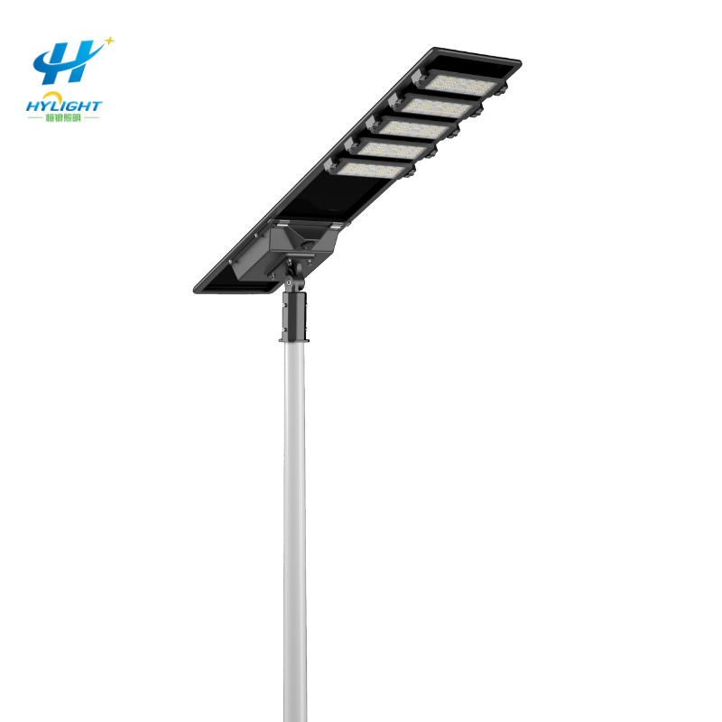
An all-in-one solar street light may need fewer external cables than a split system, but it still needs disciplined commissioning. The integrated panel, battery, controller, LED module, sensor, bracket and housing must arrive in the correct condition, face the available solar resource, aim light at the approved area, run the approved controller profile, respond correctly to dusk and motion, recover charge after operation, and leave a traceable warranty baseline.
A light that switches on once during installation has passed only a momentary functional check. It has not proved that the correct serial-numbered product was installed, that transport mode was cleared, that the intended dimming schedule is stored, that the sensor covers the road rather than nearby movement, or that the battery can replenish the energy used overnight.
This guide is for municipal owners, EPC contractors, distributors, installers, developers and operators who need a repeatable commissioning and handover package. Model-specific instructions, the approved energy and photometric design, local regulations, qualified installation practice and the contract acceptance plan always control.
GEO Summary
- Commissioning begins at receiving: match product and battery/controller identities to the approved schedule, record transport/storage dates and conditions, inspect damage, and quarantine untraceable or compromised units.
- Apply the exact model’s activation and first-charge instruction. Do not impose one universal charging time, voltage or state-of-charge rule across different batteries, controllers and shipping conditions.
- Record coordinates, mounting height, pole/bracket, product mass and wind interface, panel azimuth/tilt, luminaire aim, seasonal shading and nearby artificial-light sources before power-on.
- Wake the unit from shipping/transport mode, confirm firmware and controller identity, set the approved clock and operating profile, then preserve an export, readable screen record or parameter sheet tied to the serial number.
- Test daylight/darkness control, full output, scheduled dimming, motion or radar response, return-to-baseline timing, indicator/fault behavior and remote/communication functions using the manufacturer-approved test method.
- Observe the first complete night and the following charge period. Record start/end battery indicators or controller data, operating scenes, charge recovery, alarms, weather and exceptions without treating one sunny day as proof of worst-month autonomy.
- Handover serial-numbered configuration, photographs, test data, baseline fault status, manuals, ownership credentials, spares, maintenance and warranty evidence so later diagnosis compares like with like.
- For a project-specific proposal, send Henlyte the site coordinates, road/area geometry, mounting height and spacing, lighting criteria, operating profile, climate/solar conditions, quantity, destination and required data/acceptance format.
The Short Answer: What Should Commissioning Prove?
Commissioning should prove that each installed all-in-one solar street light matches the approved configuration and can harvest, store and deliver energy through the contract-defined lighting profile while remaining mechanically secure, controllable, diagnosable and maintainable.
A practical acceptance chain answers seven questions:
- Was the correct unit installed? Product, panel, battery, controller, LED, optic, sensor, firmware and accessories are traceable.
- Was it stored and activated correctly? Transport mode, isolation, first charge and storage limits follow the exact model procedure.
- Can it collect energy at this location? Orientation, tilt, shading, soiling and obstruction records match the approved solar basis.
- Does it light the right area? Mounting height, bracket, aim, optic and programmed output match the photometric design.
- Does the controller behave as intended? Dusk/dawn, time blocks, dimming, motion, low-energy protection and communications are configured and witnessed.
- Can it recover? The first night and following charging period show a credible, recorded baseline without hidden faults.
- Can the owner diagnose it later? Serials, settings, logs, photographs, access, manuals, spares and warranty rules are handed over.
Henlyte’s all-in-one solar street light category can establish the product architecture. The commissioning sheet should then name the exact configuration rather than relying on a catalogue wattage.
Separate Design Approval From Site Commissioning
Commissioning does not replace the worst-month energy budget, structural check or photometric calculation. Those decisions should be approved before procurement. Field work verifies that the approved assumptions were implemented and establishes an operating baseline.
Freeze these inputs before delivery:
- site coordinates and installation layout;
- road, path, parking, compound or public-area geometry;
- mounting height, spacing, setback and bracket orientation;
- required illuminance/uniformity or other lighting criteria;
- luminaire optic, output/current setting and aim;
- hourly operating profile, dimming scenes and motion behavior;
- accepted solar-resource, shading, temperature, soiling and autonomy basis;
- panel, battery, controller, sensor and LED configuration;
- firmware/profile version and access/ownership plan;
- pole, bracket, mass, projected area, fastener and wind-load interface;
- sample, hold-point, observation-period and acceptance requirements.
Use the all-in-one solar street light worst-month energy budget guide to align panel, battery, night load, autonomy and recovery before commissioning begins.
Build a Serial-Numbered Receiving and Storage Record
Integrated products concentrate several critical components in one housing. A receiving record should identify what arrived and whether its stored condition may affect commissioning.
For each unit or approved batch, record:
- project and pole/location mark;
- product model and serial number;
- panel, battery, controller, LED/driver, sensor and communication identifiers available under the approved inspection scope;
- firmware/profile shipped from the factory;
- production, shipping and receipt dates;
- transport-mode or isolation status;
- package and product condition;
- storage start/end dates, temperature/environment and charge-maintenance instruction;
- accessories, remote controls, keys, mounting hardware, cables, manuals and spare parts;
- damage, shortage, quarantine and disposition.
Inspect for cracked panel glass or laminate, frame distortion, damaged LED lens, loose housing parts, bent brackets, coating damage, opened seals, crushed connectors, corrosion, water marks, missing fasteners, unreadable labels and signs of impact. Do not energize a suspect lithium-battery assembly until the manufacturer or authorized technical party has assessed it.
Control storage time and battery condition
Battery state can change during transport and storage. The approved instructions should define switch position, allowable storage environment, inspection interval and any recharge requirement. Record compliance instead of assuming every unit leaves the warehouse fully charged.
If storage exceeds the declared limit or the battery indicator is abnormal, place the unit on hold and obtain a documented recovery or test method. Do not mask an uncertain battery state by changing the night profile before baseline evidence is captured.
Apply the Exact First-Charge and Activation Instruction
Some integrated lights ship switched off, electronically isolated or in transport mode. Some require exposure to sunlight before normal service; others use a service connector, remote command or physical switch. The correct sequence depends on the model, battery management system and controller.
The commissioning plan should state:
- shipped mode and how it is identified;
- activation method and authorized tool or remote;
- pre-activation battery/indicator check;
- model-specific first-charge condition and duration, if required;
- whether the luminaire load must remain disabled during initial charging;
- safe method for confirming battery/controller connection;
- expected indicator, screen or communication status;
- action for low-voltage, temperature, communication or battery faults;
- point at which the unit is released for installation or night testing.
Record the instruction revision and result against the product serial. Avoid universal rules such as “charge for one day” or “accept above a fixed voltage.” Battery voltage interpretation depends on chemistry, series configuration, temperature, rest period, load and controller behavior.
Release the Site, Pole, and Bracket Interface
An integrated head makes panel orientation and luminaire aim part of the same mechanical installation. Survey the site before lifting.
Location and solar access
Record coordinates, pole mark, horizon and shading photographs, compass reference, nearby trees/buildings/signs, seasonal obstruction risk, dust/salt/snow exposure, drainage/flood condition and nearby artificial lighting. A clear panel at midday is not enough if it is shaded during the project’s important charging window.
The panel normally faces toward the equator, but final azimuth and tilt must follow the approved site design and product adjustment range. Record the installed values and how they were measured.
Lighting geometry
Confirm mounting height, pole spacing, setback, road/area orientation, bracket outreach, luminaire rotation/tilt and optic. If the integrated construction cannot achieve both the approved solar orientation and photometric aim, stop and review the layout or product architecture. Do not sacrifice one silently.
Henlyte’s adjustable-angle integrated solar street light illustrates why adjustment range, locking and installed wind loading should be reviewed together.
Mechanical and structural checks
Verify:
- approved pole and bracket model;
- product mass and projected area used in the pole/bracket check;
- spigot or mounting interface dimensions;
- insertion depth or connection detail;
- fastener grade, washers, locking method and manufacturer tightening instruction;
- cable, switch, indicator, sensor and service access;
- drainage and ventilation paths;
- gasket, gland, cover and unused-port condition;
- corrosion separation between dissimilar materials where designed;
- bracket/pole verticality and final head stability.
Use calibrated tools where the contract requires recorded torque or tension. Photograph the final installed interface and witness marks if used. Recheck critical fasteners after the defined settling or observation stage.
Wake the Controller and Capture the Approved Configuration
The controller profile is part of the delivered lighting system. Treat settings as controlled project data.
Record:
- controller manufacturer/model and hardware revision;
- firmware/application version;
- product and pole serial association;
- time, date and timezone or astronomical basis;
- dusk and dawn detection logic;
- programmed output and duration for each time block;
- motion/radar/infrared mode, sensitivity, detection range or level, delay and return state as applicable;
- battery protection and low-energy behavior approved for the project;
- temperature protection behavior;
- communication address, network and ownership where fitted;
- remote-control type and access;
- parameter checksum, profile ID, export file, screen set or signed parameter sheet;
- authorized person and date of change.
Do not accept “factory default” without the actual parameter record. Defaults can change by firmware, order, market or production batch. If installers use handheld remotes, control their identity and prevent neighboring units from being changed unintentionally.
The integrated solar street light for outdoor illumination can start a configuration discussion, but the accepted controller record should be specific to the site.
Perform Safe Daytime Functional Tests
Use the manufacturer-approved commissioning or test mode. Covering the panel can simulate darkness for some products, but it may not be suitable for every sensor/controller, and a brief cover test does not reproduce a full dusk transition.
Verify:
- Normal status: controller, battery, panel and LED indicators show the expected state.
- Day/night response: the unit enters the intended test or night state and returns without an unexplained fault.
- LED output: all LED sections operate without visible flicker, partial failure, abnormal color or thermal warning.
- Dimming scenes: each programmed level or time block can be confirmed through the approved service/test function.
- Motion response: the correct zone triggers the boost, the intended level is reached, and the unit returns after the approved delay.
- Interference check: adjacent traffic, vegetation, vibration, radio sources or artificial lights do not create obvious false triggering or prevent dusk recognition.
- Communication: address, signal, data timestamp, commands and alarm reporting work where monitoring is supplied.
- Fault behavior: current alarms and diagnostic codes are read and recorded; faults are resolved rather than cleared without cause.
Test representative sensor approaches from the actual road, path or area. A sensor that reacts to an installer below the pole may still miss vehicles at speed or trigger on movement outside the intended zone.
Observe the First Complete Night
A first-night record connects the installed profile to real operation. It is a commissioning baseline, not proof of every season.
Record:
| Observation | What to capture | Acceptance link |
|---|---|---|
| Before dusk | Weather, panel condition, controller status, battery indicator/data and faults | Ready for night |
| Dusk transition | Time, artificial-light interference and initial output | Dusk logic |
| Early evening | Full/high scene, optic/aim and visible defects | Lighting design |
| Dim period | Change time, commanded and observed level | Profile schedule |
| Motion events | Approach, boost level, detection consistency and return delay | Sensor plan |
| Overnight | Alarms, unexpected cycling, outage or low-energy behavior | Control narrative |
| Pre-dawn | Required minimum scene and remaining status | Service promise |
| Dawn transition | Switch-off time and residual faults | Dawn logic |
Where field photometric measurements are required, use the approved grid, calibrated meter, geometry, weather and scene. Confirm that the controller output state during measurement matches the state used in the design file.
If a unit fails, preserve its settings, status and conditions before resetting or swapping components. A silent reset may erase the evidence needed to distinguish configuration, installation, energy, sensor, battery or hardware causes.
Check the Following Charge and Recovery Period
The system should begin replenishing the energy used overnight. Record evidence appropriate to the supplied controller: charging state, panel power/energy, battery state or voltage/current data, temperature, fault history and time. Use only parameters the product can report reliably.
Compare units under similar exposure and note weather. Investigate outliers such as:
- no charging indication under clear conditions;
- charging that starts or stops unexpectedly;
- one unit consistently below comparable units;
- low-voltage protection after a normal first night;
- temperature alarms;
- state data that jumps implausibly;
- a profile that consumes more energy than the approved schedule;
- partial shading or incorrect orientation;
- controller time or firmware mismatch.
The acceptance plan should define whether one full night plus following day is a configuration check or part of a longer observation period. A sunny commissioning window cannot prove worst-month autonomy. Conversely, one cloudy day does not automatically prove a product defect. Preserve the energy-model basis and compare measured evidence over the agreed period.
Establish a Fault and Warranty Baseline
At handover, every pole should have a known status. Record active and historical fault codes, resets, battery protection events, communication losses, over-temperature events, sensor exceptions, component replacements and profile changes.
For any exception, capture:
- pole/product serial;
- date/time and environmental conditions;
- installed configuration and firmware/profile;
- symptom and fault code;
- panel, battery, load and controller data available;
- photographs or screenshots;
- temporary action;
- technical diagnosis;
- approved repair or replacement;
- repeated tests and final result.
Do not close a fault only because the lamp illuminates after a reset. Confirm the cause and repeat the affected night/charge or sensor test.
Agree the warranty evidence before handover. The owner should know which data it may collect, who owns the account or gateway, how configuration backups are stored, which seals may be opened, what maintenance is required, and how a claim is submitted without compromising safety or coverage.
Use a Commissioning Sheet That Connects Every Discipline
| Field group | Minimum record |
|---|---|
| Identity | Project, pole/location, product serial, component/firmware/profile references |
| Receiving/storage | Dates, condition, isolation, storage environment and charge-maintenance status |
| Site | Coordinates, shading/horizon, artificial light, environment and photographs |
| Mechanical | Pole/bracket, mounting height, fasteners, locking, aim, azimuth/tilt and ingress inspection |
| Activation | Transport mode, first-charge instruction, initial status and release |
| Controls | Clock, dusk/dawn, time blocks, dim levels, sensor, low-energy logic and exported settings |
| Function | LED, dimming, motion, communication, indicators and fault checks |
| Night | Dusk, scenes, motion events, pre-dawn, dawn and photometric results if required |
| Recovery | Following charge status/data, weather, outliers and observation-period result |
| Closeout | Exceptions, repairs, retests, as-builts, training, spares, access and warranty |
Use one sheet per unit or a controlled digital register with the same traceability. Batch acceptance may be appropriate for some factory or receiving checks, but installed orientation, serial, controller profile and fault status should remain location-specific.
Plan Samples, Hold Points, and Observation Periods
Large projects may use staged commissioning:
- approve a first-article or pilot installation;
- close civil, bracket, orientation and controller-profile issues;
- release a controlled installation batch;
- perform 100 percent identity, mechanical, setting and basic function checks as specified;
- conduct extended night, photometric or energy observations on the contract sample;
- expand sampling or correct the batch when a systemic defect appears;
- freeze the accepted profile and as-built register.
The sample size and acceptance rule should be risk-based and stated in the contract. Do not invent a percentage after failures appear. A repeated wrong profile, fastener, orientation or firmware revision is a batch-control problem even if only one unit was sampled.
Prepare the Owner Handover Package
Provide:
- approved and as-built layout with pole IDs and coordinates;
- product and component serial/model register;
- panel azimuth/tilt, luminaire aim and mounting-height record;
- foundation/pole/bracket and critical-fastener records;
- controller firmware, profile ID, parameter export and change history;
- first-charge/activation and functional-test sheets;
- first-night, following-charge and extended-observation data required by contract;
- fault, nonconformance, repair and retest closeout;
- photometric measurements where required;
- operation, maintenance, cleaning and troubleshooting manuals;
- wiring/connection and replacement procedures allowed for the product;
- remote controls, gateways, account/admin ownership and secure credential handover process;
- spares, special tools and parameter backup;
- training and authorized service contacts;
- warranty matrix, claim evidence and response commitments.
Use Henlyte’s broader solar street light range to compare applications. If panel orientation, battery thermal location or component replacement needs more flexibility, review whether a split solar street light offers a better project interface.
All-in-One Solar Street Light RFQ Checklist
- Site coordinates, layout, road/area dimensions, obstacles, horizon/shading photographs, climate, dust/salt/snow/flood exposure and cleaning assumptions.
- Required maintained lighting result, mounting height, spacing, setback, optic, CCT, full/dim scenes and motion behavior.
- Approved solar-data source, worst-month basis, autonomy/recovery requirement and observation-period acceptance.
- Product model, panel Wp/area, battery chemistry/usable energy, controller, sensor, LED/driver, firmware, profile and communication option.
- Shipping mode, storage limits, charge-maintenance and first-activation instruction.
- Pole/bracket, mass, projected area, adjustment range, fastener/locking, sealing, corrosion and maintenance-access requirements.
- Controller clock, dusk/dawn, time blocks, dimming, motion, low-energy behavior, access rights, configuration export and change control.
- Daytime functional, first-night, following-charge, photometric, fault and retest requirements.
- Serial-numbered as-built register, manuals, wiring/connection diagrams, training, spares, credentials/ownership, warranty and service response.
- Quantity, destination, Incoterm, delivery/storage dates, installation responsibility, pilot batch, schedule and authorized contacts.
Send these inputs through Henlyte’s project inquiry page so the offered integrated system and commissioning records can be tied to the site.
Common Commissioning Red Flags
- Product serials, battery/controller configuration or firmware are not tied to pole locations.
- Units were stored for an unknown period with no isolation or recharge record.
- Every model receives the same first-charge rule even though the manuals and batteries differ.
- Panel orientation is checked, but luminaire aim and road geometry are not.
- The bracket can meet either solar tilt or lighting aim, but not both, and no one records the conflict.
- “Factory default” is accepted without a parameter export or readable setting record.
- Motion is tested by waving beneath the pole rather than from the intended detection path.
- One brief daytime cover test is called full commissioning.
- The first night is observed, but the following charging period is not.
- Low-voltage or temperature alarms are reset without preserving conditions and cause.
- A sunny week is claimed as proof of worst-month autonomy.
- Remote account ownership remains with an installer, salesperson or unidentified phone.
- The warranty requires data that the owner cannot access or preserve.
Frequently Asked Questions
Does every all-in-one solar street light need the same first charge?
No. Activation and first-charge requirements depend on the exact product, battery, controller, shipping mode and storage history. Follow the current model instructions and record the result against the serial number.
How do installers test a solar street light during the day?
Use the manufacturer’s approved test mode, remote command or darkness-simulation method. Briefly covering the panel works for some controllers but not all. Confirm that the test method does not create a false result or unsafe condition.
What controller settings should be recorded?
Record firmware/profile ID, clock and time basis, dusk/dawn logic, every output/time block, motion settings, return delay, low-energy and temperature behavior, communication identity and a parameter export or complete readable screen record.
Is one successful night enough for acceptance?
One complete night is useful to verify installed configuration and scenes. It does not prove worst-month autonomy or long-term reliability. The contract should define the following charge check and any longer seasonal or energy observation.
What should be recorded if a light fails during commissioning?
Preserve the serial, location, configuration, profile, time, weather, shading, battery/controller status, fault code, photographs and actions before resetting or replacing parts. Repeat the affected tests after the approved correction.
When should a split solar street light be considered instead?
Consider a split architecture when the panel needs independent orientation or larger area, the battery needs a different thermal/service location, or the project requires easier component replacement. Compare that flexibility with the extra wiring, connectors and installation work.
Request a Site-Specific All-in-One Solar Street Light Proposal
Share the coordinates, layout, mounting height and spacing, lighting criteria, full/dim operating profile, solar and climate basis, shading photographs, pole/bracket constraints, quantity, destination, observation period, data requirements and warranty expectations. Henlyte can then align the product configuration, commissioning sheet and handover evidence with the actual project.